Follow-up pipeline groove

A pipeline trough and follow-up technology, applied in the field of pipeline troughs, can solve the problems of long relocation period, poor versatility and high risk of drilling rigs, and achieve the effects of eliminating hoisting by cranes, facilitating pipeline maintenance and reducing operating costs.

Active Publication Date: 2014-07-09
ZYT GASOLINEEUM EQUIP
View PDF8 Cites 2 Cited by
  • Summary
  • Abstract
  • Description
  • Claims
  • Application Information

AI Technical Summary

Problems solved by technology

[0003] There are currently two types of existing solutions. One is to install a simple cable bracket between the top layer of the drill floor and the base. Every time the bracket is disassembled and relocated, the bracket, cables, and water and gas pipelines must be fixed and disassembled repeatedly, resulting in a long cycle and heavy workload for the drilling rig
[0004] The other is the special folding pipeline trough, where cables and water and gas pipelines are installed in the pipeline trough at a low position, and can be lifted up with the drilling rig as a whole. A transfer box is installed on the pipeline trough, but because the size of each part of this kind of pipeline trough is fixed, each drilling rig must be tailor-made for each type of rig, and the versatility is not strong, and some transfer boxes are installed on the uppermost pipeline trough. High altitude operation, high risk

Method used


Image

  • Follow-up pipeline groove
  • Follow-up pipeline groove
  • Follow-up pipeline groove

Examples


Embodiment Construction

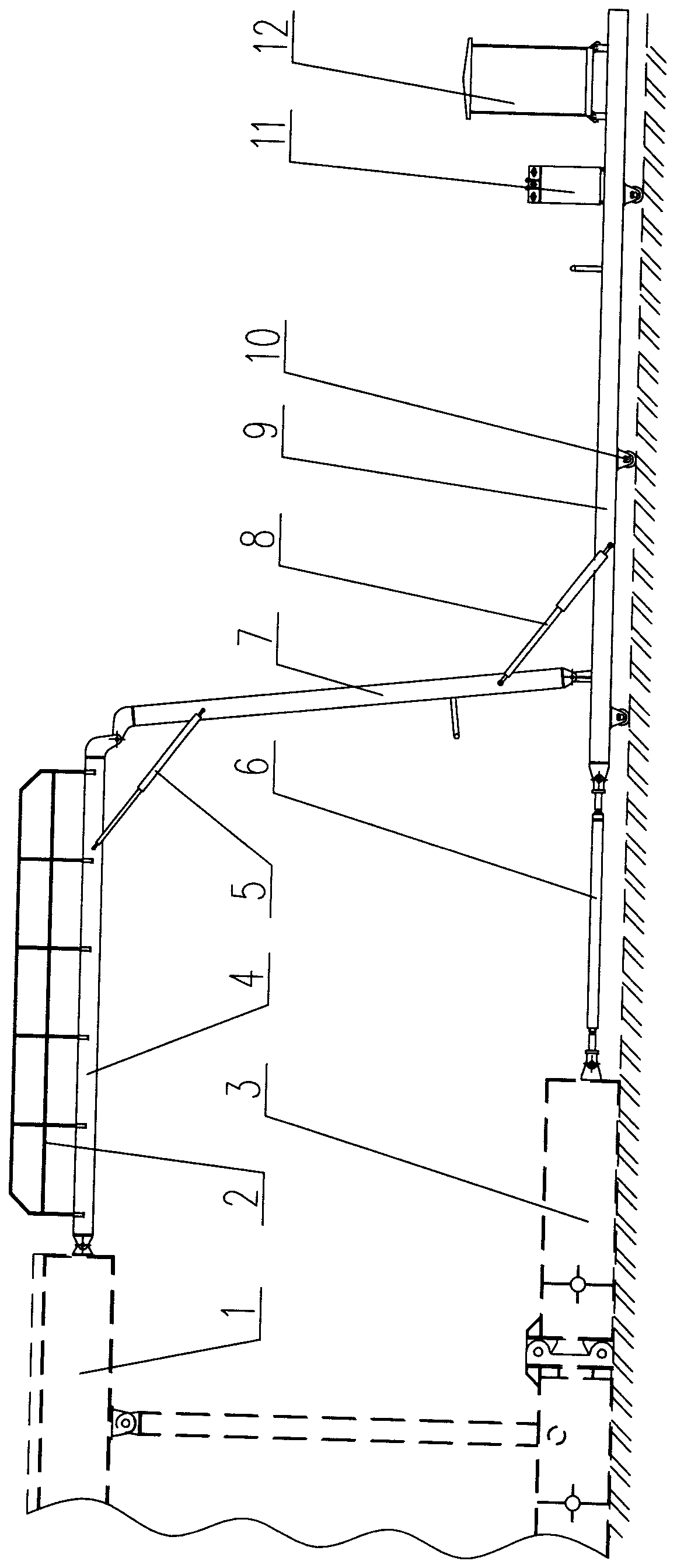
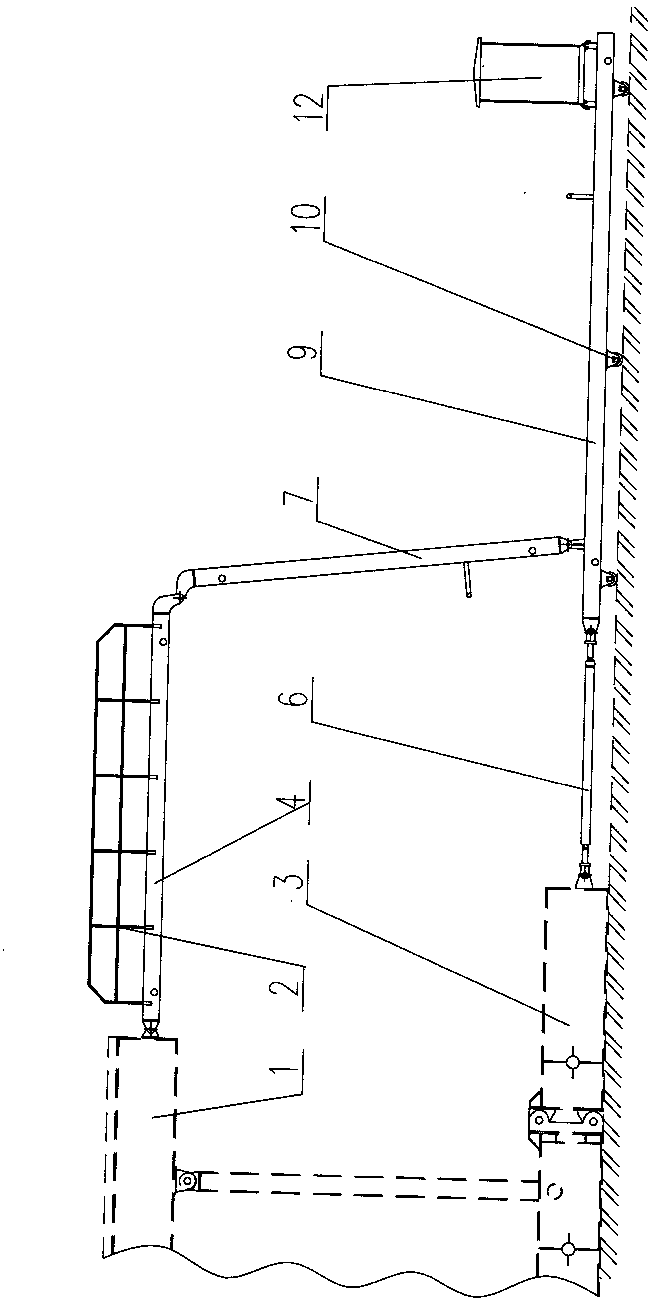
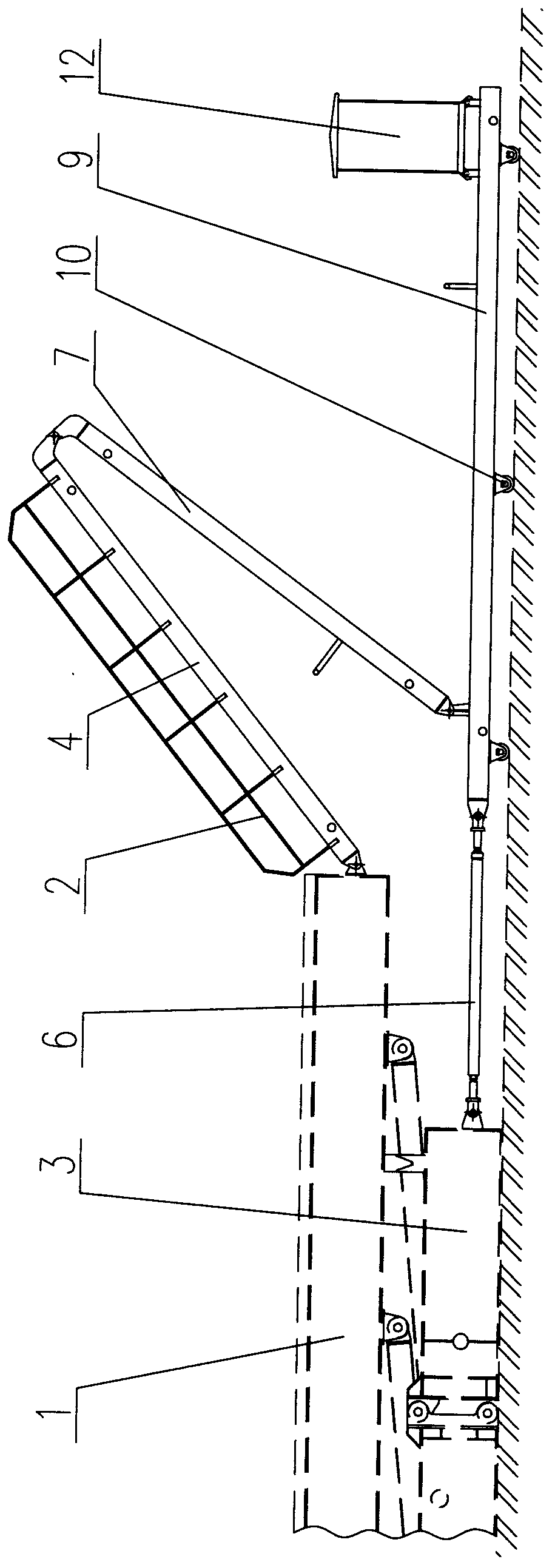
[0021] exist figure 2 , image 3 Among them, a follow-up pipeline trough is mainly composed of a high-level pipeline trough 4, a middle-level pipeline trough 7 and a low-level pipeline trough 9. The high-level pipeline trough 4 is provided with a guardrail 2, one end of which is hinged to the top floor 1 of the drill floor, and the other end Hinged with the middle pipeline trough 7, the front end of the low pipeline trough 9 is connected to the drill floor base 3 through an adjustable telescopic pull rod 6, and the other end of the middle pipeline trough 7 is hingedly connected to the low pipeline trough 9 near the telescopic pull rod 6 , the lower part of the low-level pipeline trough 9 is provided with a roller 10, and its end away from the telescopic pull rod 6 is provided with a transfer box 12.

[0022] When the drilling rig is at a low position, the high-level pipeline trough 4 and the top floor of the drill floor 1, the high-level pipeline trough 4 and the middle pipe...


PUM


Abstract

The invention provides a follow-up pipeline groove, and relates to the technical field of auxiliary equipment of drill rigs. The follow-up pipeline groove mainly comprises a high-position pipeline groove, a middle-position pipeline groove and a low-position pipeline groove. Guardrails are arranged on the high-position pipeline groove, one end of the high-position pipeline groove is hinged to a top layer of a drill floor, the other end of the high-position pipeline groove is hinged to the middle-position pipeline groove, the front end of the low-position pipeline groove is connected with a base of the drill floor by an adjustable telescopic draw bar, the other end of the middle-position pipeline groove is connected onto the low-position pipeline groove in a hinged manner and is close to the telescopic draw bar, rollers are arranged on the lower portion of the low-position pipeline groove, and a transfer case is arranged at the end, which is far away from the telescopic draw bar, of the low-position pipeline groove. The follow-up pipeline groove has the advantages that when the follow-up pipeline groove is mounted at a low position, the high-position pipeline groove is hinged to the top layer of the drill floor by the aid of an operation cylinder without being hoisted by a crane, and the length of the telescopic draw bar can be adjusted, so that a folding angle of the follow-up pipeline groove can be controlled, and the follow-up pipeline groove is applicable to different types of drill rigs provided with drill floors with different heights; the transfer case is mounted on the low-position pipeline groove, is convenient to operate and is safe and reliable, and the transfer case and the follow-up pipeline groove can form an integral transport unit.

Description

technical field [0001] The invention relates to a pipeline trough of an electric drilling rig for an oil cluster well, in particular to a follow-up pipeline trough. Background technique [0002] The top floor of the cluster well electric drilling rig used in the oil drilling field is high from the ground, generally ranging from 6 meters to 11 meters depending on the model of the drilling rig, so the power supply cables required for various equipment on the top floor of the drill floor, Water supply and gas supply pipelines must be able to be laid from the ground to the top of the drill floor, and the cables and water and gas pipelines are required to be able to move with the drilling rig as a whole. [0003] There are currently two types of existing solutions. One is to install a simple cable bracket between the top layer of the drill floor and the base. Every time the bracket is disassembled and relocated, the bracket, cables, and water and gas pipelines must be fixed and ...

Claims


Application Information

Patent Timeline
Patent Type & Authority Applications(China)
IPC IPC(8): F16L3/01F16L3/015H02G11/00H02G3/04
CPCF16L3/01H02G3/045H02G11/00
Inventor 韩洪波张建军魏殿举王维忠张子胜余磊李张英李晓洛
Owner ZYT GASOLINEEUM EQUIP
Why Eureka
Try Eureka