Small end cover end face height guide rail inspection tool

A technology for guide rails and end caps is applied in the field of small end cap end face height guide rail inspection tools, which can solve the problems of high error rate of manual measurement, low detection efficiency, time-consuming and laborious, etc., and achieves the advantages of manual operation, low production cost, and easy replacement. Effect

Active Publication Date: 2017-01-04
CHANGSHA BODA MACHINERY PARTS CO LTD
View PDF8 Cites 0 Cited by
  • Summary
  • Abstract
  • Description
  • Claims
  • Application Information

AI Technical Summary

Problems solved by technology

[0005] The traditional method is manual measurement, using calipers and gauges to measure the reference height values ​​of a1, b1, c2 or a2, b2, c2 one by one, and then comprehensively evaluate whether the size of the end cap is qualified; this method is time-consuming and laborious, and the detection efficiency is low , manual measurement has a high error rate, is prone to fatigue, has certain technical requirements for operators, and the measurement itself has large errors and is not accurate

Method used


Image

  • Small end cover end face height guide rail inspection tool
  • Small end cover end face height guide rail inspection tool
  • Small end cover end face height guide rail inspection tool

Examples


Embodiment 1

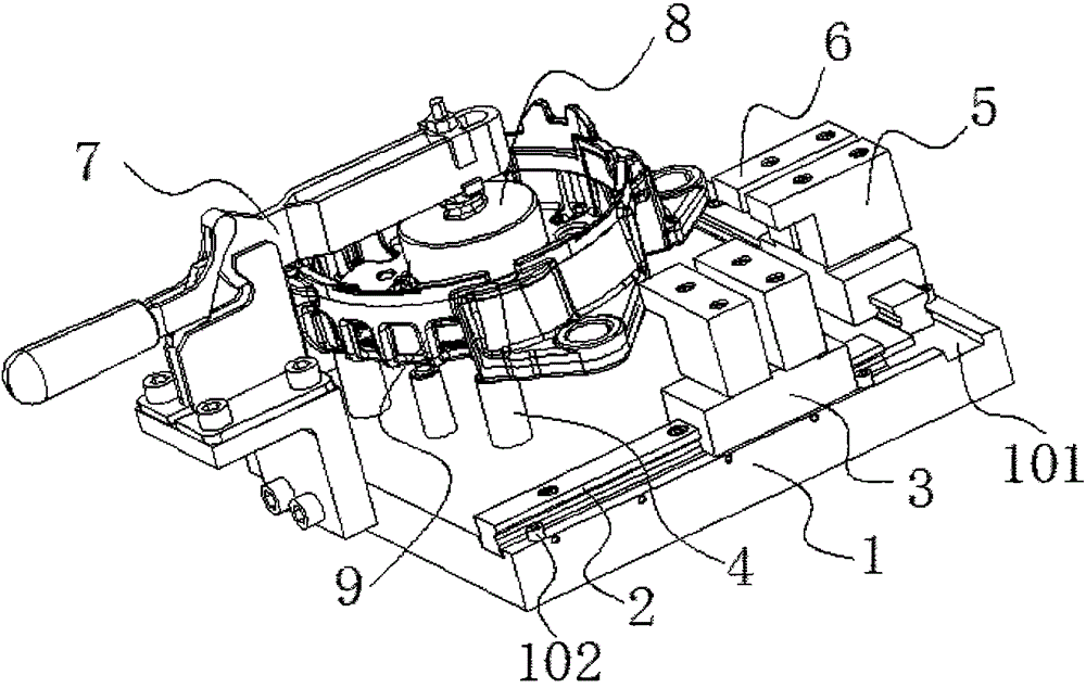
[0026] Such as Figure 3-4 As shown, the specific structure of the present invention is as follows: it includes a base plate 1, a clamping mechanism 7 is provided on the left side of the base plate 1, a pressing plate 8 is provided at the lower end of the clamping mechanism 7; a guide rail 2 is provided on the side of the base plate 1 , the guide rail 2 is provided with a slider 3 , and the slider 3 is provided with a stop gauge 5 and a through gauge 6 . A positioning column 4 is arranged in the middle of the bottom plate 1 . A guide rail groove 101 is formed on the side of the bottom plate 1 , and the guide rail 2 is fitted in the guide rail groove 1 .

[0027] Preferably, two adjacent sides of the bottom plate 1 are provided with guide rail grooves 101 , and the guide rail grooves 101 are vertically staggered, and the guide rails 2 are fitted therein. A block 102 is provided near the end of the guide rail 2 . The stopper 102 is arranged on the bottom plate 1 near the end ...

Embodiment 2

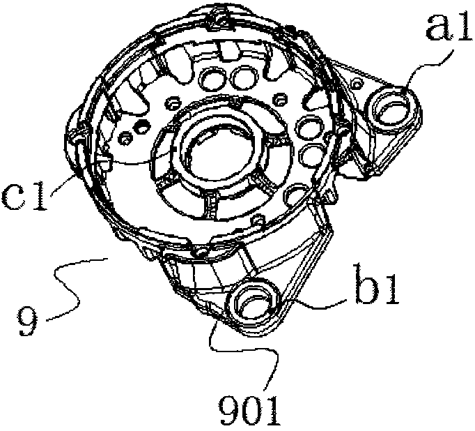
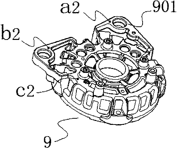
[0030] Such as Figure 5 As mentioned above, this embodiment follows the basic structure of the previous embodiment. The difference is that the setting of the through gauge 6 and the stop gauge 5 are different. The side of the through gauge 6 is provided with a measuring groove 601, and the height of the stop gauge 5 is lower than that of the through gauge. Gauge 6 height. The measurement mode of Embodiment 1 is to indirectly measure the heights of the a1, b1 surfaces and c2 of the hanging angle 901 of the end cover 9, that is, the height from the plane positioning surface of the end cover 9 to the upper end surface of the hanging angle hole of the hanging angle 901, thereby judging Whether the product is qualified; here embodiment two is the height of the a2, b2 surface and c2 of the hanging angle 901 of the end cover 9 indirectly, that is, the plane positioning surface of the end cover 9 to the lower end surface of the hanging angle hole of the hanging angle 901 Height, in ...


PUM


Abstract

The invention belongs to the field of clamp detection devices, and discloses a small end cap end face height guide rail detection device. The device comprises a bottom plate, wherein the left of the bottom plate is provided with a clamping mechanism, the lower end of the clamping mechanism is provided with a pressing plate, the side edge of the bottom plate is provided with a guide rail where a sliding block is arranged, and the sliding block is provided with a non-go gauge and a go gauge. According to the small end cap end face height guide rail detection device, in terms of the principle of the non-go gauge and the go gauge, the detection process is visual, detection efficiency is high, the error rate is low, the device has no requirements for techniques of operators, manual operation is facilitated, fatigue is not prone to occurrence, work precision of the detection device is high, manufacturing cost is low, the device is easy to manufacture and machine, spare parts are easy to replace, and interchangeability is high.

Description

technical field [0001] The invention belongs to the field of fixture inspection tools, in particular to a guide rail inspection tool for the height of a small end cover end face. Background technique [0002] In the manufacturing process of commonly used small commercial or vehicle generators or engines, the end covers of generators or engines are mostly made of metal casting. In order to ensure rigidity and reduce weight, they are mostly cast from aluminum alloy; in the casting process Generally, it is necessary to leave a machining allowance, and then perform cutting processing to become a finished product. [0003] In order to meet the assembly requirements of the end cover, it is necessary to control the relevant dimensions of the end cover, so it is necessary to measure the size after the manufacture is completed to ensure compliance. figure 1 , figure 2 The middle letters are expressed as: a1, b1 are the upper end faces of the hanging angle holes of the hanging angl...

Claims


Application Information

Patent Timeline
Patent Type & Authority Patents(China)
IPC IPC(8): G01B5/02
Inventor 周春林
Owner CHANGSHA BODA MACHINERY PARTS CO LTD
Why Eureka
Try Eureka