Composite busbar and three-phase inverter circuit

A technology of compound busbar and busbar

Active Publication Date: 2014-07-09
CRRC YONGJI ELECTRIC CO LTD
View PDF5 Cites 21 Cited by
  • Summary
  • Abstract
  • Description
  • Claims
  • Application Information

AI Technical Summary

Problems solved by technology

[0004] The invention provides a composite busbar and a three-phase inverter circuit, which is used to solve the problem of large stray inductance of th

Method used


Image

  • Composite busbar and three-phase inverter circuit
  • Composite busbar and three-phase inverter circuit
  • Composite busbar and three-phase inverter circuit

Examples


Embodiment 1

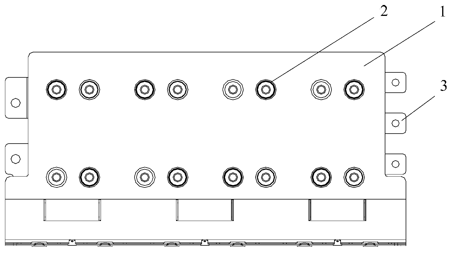
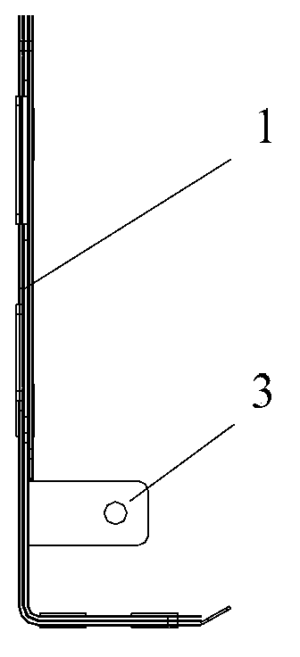
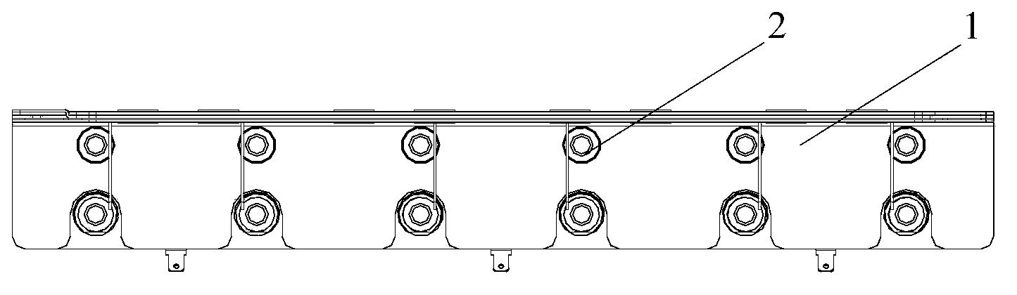
[0022] figure 1 It is the front view of the composite busbar provided by Embodiment 1 of the present invention, figure 2 It is the left view of the composite busbar provided by Embodiment 1 of the present invention, image 3 It is a top view of the composite busbar provided by Embodiment 1 of the present invention. The specific structure of the composite busbar is as follows, including busbar 1 , terminal 2 and connection part 3 .

[0023] The shape of the busbars 1 is flat, at least two of the busbars 1 are stacked together, and the adjacent busbars 1 are filled with high-dielectric-strength materials, so that the gap between the adjacent busbars 1 Keep it insulated. Terminals 2 are arranged on the busbar 1 for connecting circuit devices. The connection part 3 is arranged on the bus bar 1 and is used for connecting a DC input terminal or a circuit device.

[0024] Wherein, the busbar 1 is set in a flat shape, the width of the section is increased, and the thickness of t...

Embodiment 2

[0031] Figure 4 It is a three-dimensional schematic diagram of the composite busbar provided in Embodiment 2 of the present invention, Figure 5 It is a three-dimensional schematic diagram of the composite busbar provided in Embodiment 2 of the present invention, Figure 6 for Figure 4 A schematic diagram of part A, Figure 7 for Figure 4 Part B schematic, Figure 8 The schematic diagram of the three-phase inverter circuit provided by Embodiment 2 of the present invention. This embodiment further optimizes the technical solution of applying the composite busbar to the three-phase inverter circuit on the basis of the above embodiments. The three-phase inverter circuit includes three sets of power devices, energy storage devices, discharge resistors and composite busbars.

[0032] Wherein, the composite busbar is the composite busbar mentioned in the above-mentioned embodiment, and the composite busbar includes three busbars stacked together, and the first busbar 11 and...


PUM

PropertyMeasurementUnit
Thicknessaaaaaaaaaa
Thicknessaaaaaaaaaa

Abstract

The invention provides a composite busbar and a three-phase inverter circuit. The composite busbar comprises busbar units, terminals and connection portions. The busbar units are flat, at least two busbar units are overlapped, and the position between the adjacent busbar units is filled with high-insulating-strength materials, so that the adjacent busbar units are insulated. The terminals are arranged on the busbar units and used for being connected with circuit devices, and the connection portions are arranged on the busbar units and used for being connected with direct-current input ends or the circuit devices. The composite busbar is used for solving the problem that in the prior art, a circuit is large in stray inductance, reduces the stray inductance of the circuit, and reduces peak voltage.

Description

technical field [0001] The invention relates to electrical technology, in particular to a composite busbar and a three-phase inverter circuit. Background technique [0002] The operating system of an electric locomotive mainly includes traction system and auxiliary system, among which the traction auxiliary converter is an important device to ensure the electric locomotive to achieve electric traction, braking and auxiliary supply, and determines the stability of the high-speed operation of the electric locomotive. [0003] At present, the electrical connection of the key components in the three-phase inverter circuit of the traction auxiliary converter, such as the insulated gate bipolar transistor (Insulated Gate Bipolar Transistor, IGBT), the supporting capacitor and the absorbing capacitor, is usually connected by cables or copper bars. connect. In the working state of the traction auxiliary converter, due to the inductance of the IGBT itself and the parasitic inductanc...

Claims


Application Information

Patent Timeline
IPC IPC(8): H01R25/16H01R31/06H02M7/42
CPCH01R25/16H05K7/14329
Inventor 牛勇张丹朱杭杭赵一洁唐子辉
Owner CRRC YONGJI ELECTRIC CO LTD
Why Eureka
Try Eureka