
Piezoelectric vibration generating set and manufacturing method thereof

A technology of vibration power generation and piezoelectricity, which is applied in the field of micro energy, can solve the problems of increasing production cost and installation cost, limited deformation of piezoelectric sheets, and affecting power generation efficiency, etc., and achieves high mechanical energy conversion efficiency, improved power generation efficiency, and simple structure Effect

Inactive Publication Date: 2014-07-09
BEIJING JIAYUE TONGLEJI ELECTRONICS
View PDF5 Cites 0 Cited by
  • Summary
  • Abstract
  • Description
  • Claims
  • Application Information

AI Technical Summary

Problems solved by technology

However, the traditional piezoelectric vibration power generation device installs the piezoelectric sheet on the cantilever. When the vibration or movement occurs, the cantilever is easily bent due to the vibration. Deformation, due to the piezoelectric effect of the piezoelectric sheet, the piezoelectric sheet will generate a potential and output voltage, but due to the size limitation of the cantilever, the bending deformation is small, so the deformation of the piezoelectric sheet is also limited, affecting its power generation efficiency; Furthermore, in order to meet the high output voltage of the existing piezoelectric vibration power generation device, the cantilever has a large volume and a complicated structure, thereby increasing the production cost and installation cost

Method used


Image

  • Piezoelectric vibration generating set and manufacturing method thereof
  • Piezoelectric vibration generating set and manufacturing method thereof
  • Piezoelectric vibration generating set and manufacturing method thereof

Examples


Embodiment Construction

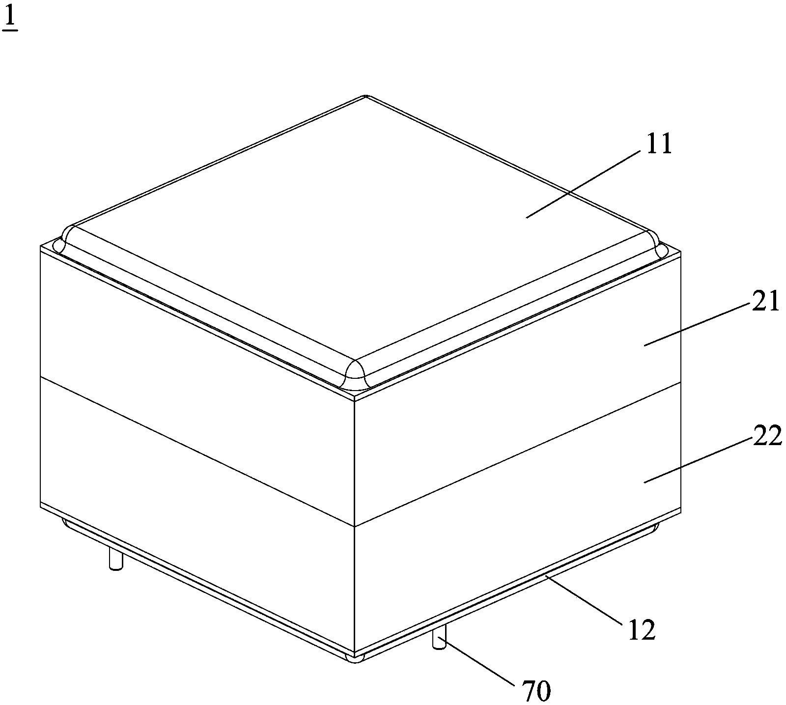
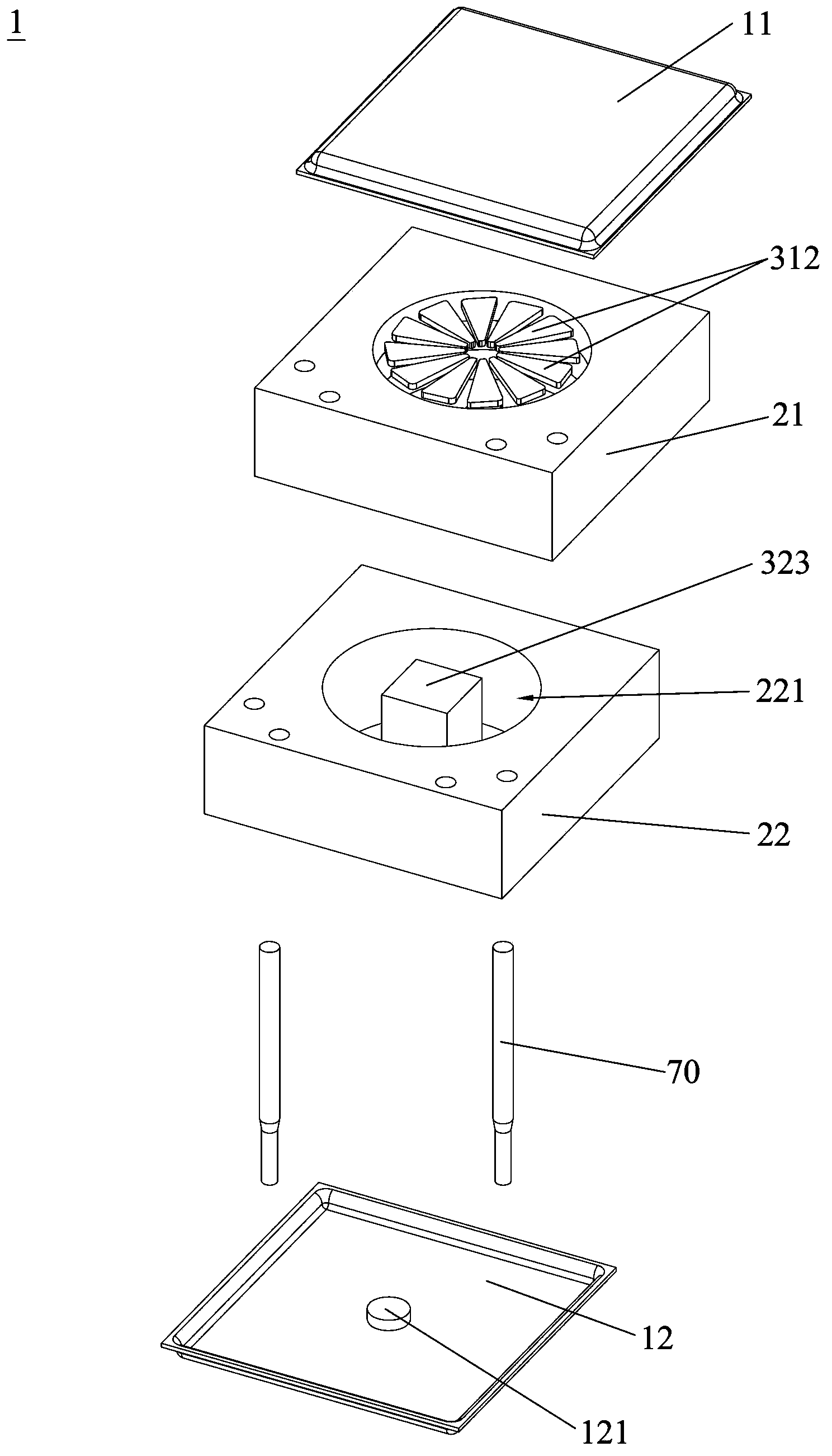
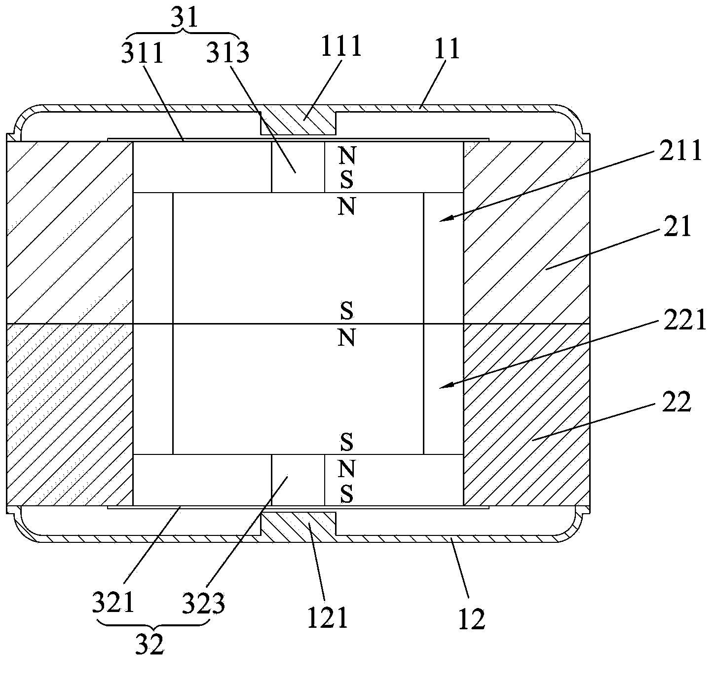
[0043] Embodiments of the present invention will now be described with reference to the drawings, in which like reference numerals represent like elements. The piezoelectric vibration power generation device 1 of the present invention includes a bottom cover, a base, at least two power generating units and at least two conductive welding pins. The power generation unit is arranged on the base and parallel to each other, and the two bottom covers are respectively provided on two ends of the base, and the two bottom covers seal the accommodating cavity. Wherein, the base can be one, or a plurality of correspondingly connected structures.

[0044] Combine below Figure 1-Figure 12 As shown, different embodiments of the piezoelectric vibration power generation device 1 of the present invention are described respectively.

[0045] Such as Figure 1-Figure 3 As shown, in the first embodiment of the piezoelectric vibration power generation device 1 of the present invention, the pi...


PUM


Abstract

The invention discloses a piezoelectric vibration generating set which comprises bottom caps, a base, at least two generating units and at least two conductive welding pins. The generating units are arranged on the base in parallel and overlaid modes, the two bottom caps are arranged at the two ends of the base respectively in a covering mode to seal a containing cavity, and the conductive welding pins are connected with the generating units and penetrate through one bottom cap to form a conductive electrode. Each generating unit comprises an elastic plate, a piezoelectric plate and a free vibrator, the elastic plates are supported at the end of the base, the free vibrators are bonded in the middles of the elastic plates, and the piezoelectric plates are bonded on the side faces, opposite to the free vibrators, of the elastic plates. The base and the bottom caps cover the generating units to form the piezoelectric vibration generating set, the functions of self-electricity-generating and anti-falling protection in multiple space angles are achieved, generating efficiency is high, the structure is simple, the size is small, thickness is small, and cost is low. In addition, the invention further discloses a manufacturing method for the piezoelectric vibration generating set.

Description

technical field [0001] The invention relates to the field of micro energy technology, in particular to a piezoelectric vibration power generation device and a manufacturing method thereof. Background technique [0002] The rapid development and application of micro-nano electromechanical system (MEMS, NEMS) technology has driven the development of wireless sensor network technology, and has gradually realized commercial applications in the fields of industry, aerospace, communication, commerce, consumption and military affairs, but there are still challenges A very serious problem is how to ensure the power supply of these wireless sensing units and mobile communication equipment. The traditional method is to use batteries, but due to the large number of unit devices constituting the wireless sensor network and mobile communication equipment, the size is small, and the location is scattered, this requires its power supply devices to be small in size, high in efficiency, easy...

Claims


Application Information

Patent Timeline
IPC IPC(8): H02N2/18
Inventor 冯淑兰彭春雷
Owner BEIJING JIAYUE TONGLEJI ELECTRONICS
Learn More