Microwave heating device

A microwave heating device and microwave technology, applied in microwave heating, electric heating device, electric/magnetic/electromagnetic heating and other directions, can solve the problem of decreasing heating efficiency, achieve uniform and efficient heating, and suppress the effect of bottom scorching

Active Publication Date: 2014-07-09
PANASONIC CORP
View PDF10 Cites 9 Cited by
  • Summary
  • Abstract
  • Description
  • Claims
  • Application Information

AI Technical Summary

Problems solved by technology

However, in this case, the positional relationship between the opening and the microwave radiation part such as the antenna and the load also changes according to the rotation of the table or the antenna. When the magnetron is operated in a high-efficiency state (a state where the impedance on the magnetron side and the impedance on the load side are matched), the heating efficiency decreases.

Method used


Image

  • Microwave heating device
  • Microwave heating device
  • Microwave heating device

Examples


Embodiment approach 1

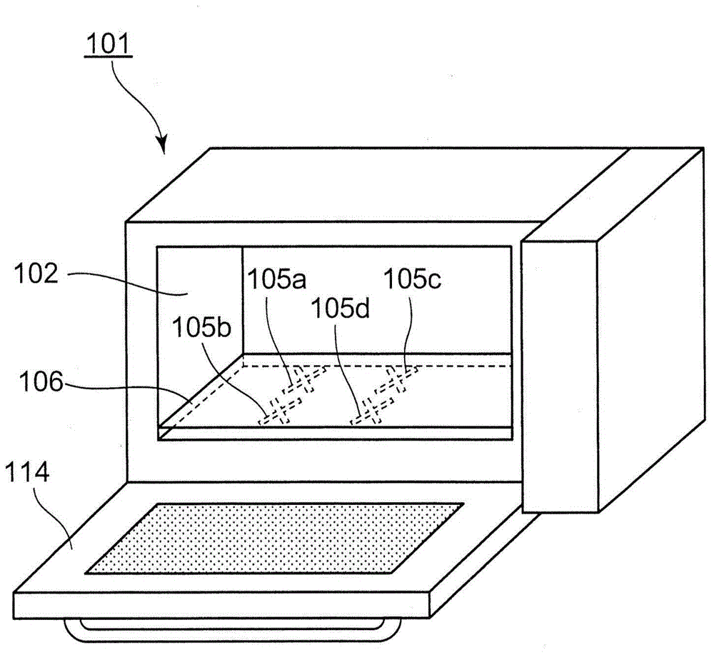
[0041] figure 1 with figure 2 It is a figure explaining the microwave heating apparatus of Embodiment 1 of this invention. figure 1 Is a perspective view showing the overall structure of the microwave heating device of the first embodiment, figure 2 The microwave generating part, the wave guide, the heating chamber, etc. which are the main parts of the microwave heating apparatus of Embodiment 1 are shown typically. in figure 2 Among them, (a) is a cross-sectional view of the heating chamber and the like viewed from above, and (b) is a cross-sectional view viewed from the front.

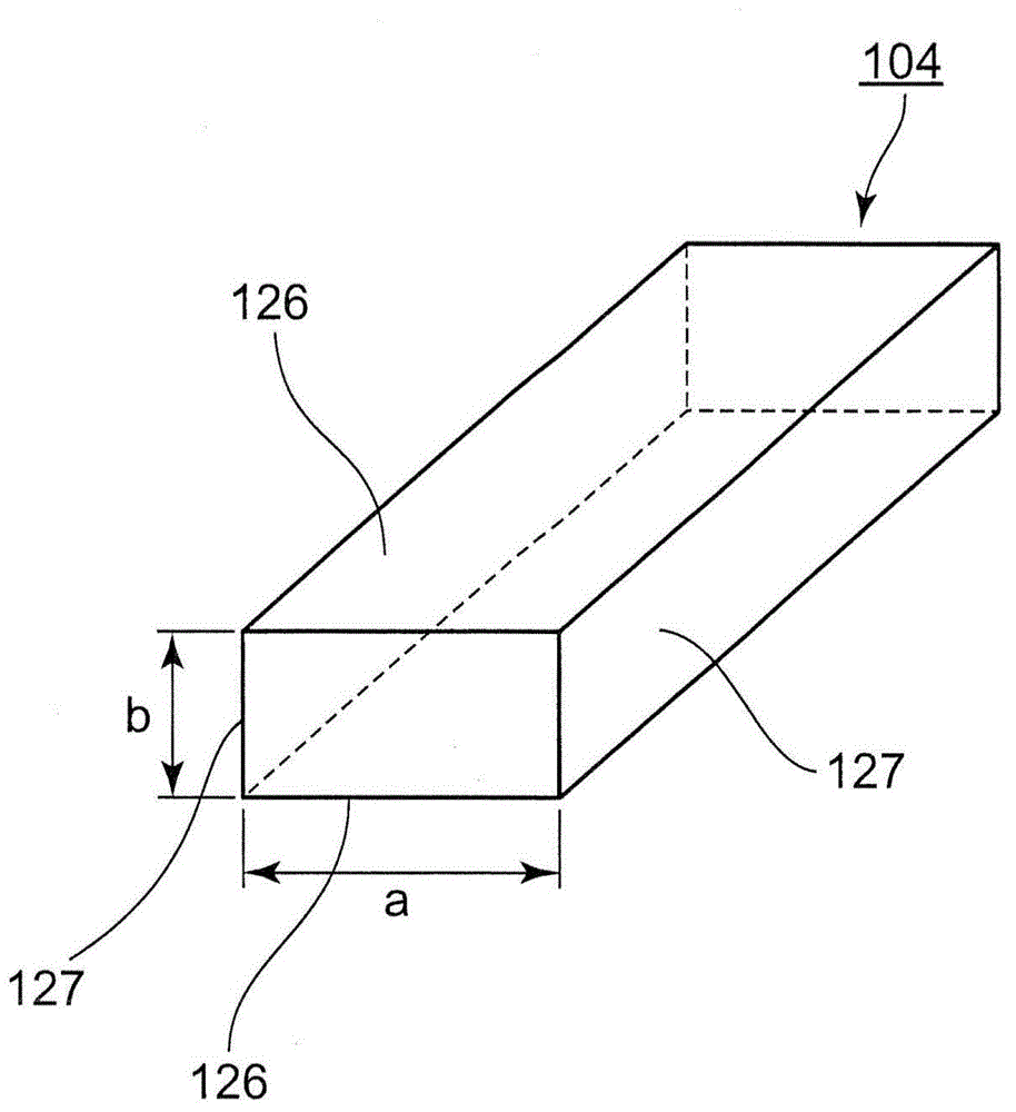
[0042] The microwave oven 101, which is a representative microwave heating device, has: a heating chamber 102 that can accommodate food (not shown) as a representative object to be heated; and a magnetron 103, which is a representative microwave generating unit that generates microwaves Waveguide 104, which introduces the microwaves radiated from the magnetron 103 into the heating chamber 102; a mic...

Embodiment approach 2

[0086] Hereinafter, a microwave heating device according to Embodiment 2 of the present invention will be described with reference to the drawings. Figure 7 The position of the antinodes and nodes of the standing wave in the chamber generated in the heating chamber 102 and the positions of the antinodes and nodes of the standing wave in the tube generated in the waveguide 104 are schematically shown in the microwave oven of the second embodiment. position. in Figure 7 (A) is a plan view of the heating chamber 102 viewed from above, (b) is a cross-sectional view along the line A2-A2 of (a), and (c) shows the opening as the microwave radiation portion and the antinode of the standing wave in the tube and An explanatory diagram of the positional relationship of the nodes, (d) is a cross-sectional view of the B2-B2 line of (a). in Figure 7 In (a), (b), (d), a solid line is used to enclose the area where the antinode of the standing wave in the warehouse is assumed to exist, and ...

Embodiment approach 3

[0099] Hereinafter, a microwave heating device according to Embodiment 3 of the present invention will be described with reference to the drawings. Figure 8 It is a figure explaining the opening shape as a microwave radiation part in the microwave heating apparatus of Embodiment 3 of this invention, for example, a microwave oven. In the structure of Embodiment 3, the difference from the structure of Embodiment 1 is the shape of the opening, and the structure of Embodiment 1 is applied in other respects.

[0100] Hereinafter, as the microwave radiation portion, an opening shape composed of at least two long holes (slits) that emit circularly polarized waves will be described.

[0101] Such as Figure 8 As shown, the openings 411 to 417 are each composed of two or more long holes. In the openings 411 to 417, the long side of at least one long hole may be in a shape inclined with respect to the microwave transmission direction (arrow 418). Therefore, it may be a shape in which lon...


PUM


Abstract

The invention provides a microwave heating device which can uniformly and efficiently heat an object to be heated without using a driving mechanism and can suppress the bottom of the object to be heated from being scorched even though the object to be heated in a small shape. The microwave heating device includes a heating chamber (102) for receiving the object to be heated, a microwave generation part (103) for generating microwaves, a wave guide pipe (104) for transmitting microwaves, a plurality of microwave radiation parts (105a, 105b, 105c, 105d) for radiating microwaves into the heating chamber (102) from the wave guide pipe (104), standing waves are generated in the heating chamber (102), and the center (144) of the bottom (108) of the heating chamber (102) carrying the object to be heated generates a part between the antinode and the node of the standing waves.

Description

Technical field [0001] The present invention relates to a microwave heating device such as a microwave oven that radiates microwaves to a heated object to perform dielectric heating. Background technique [0002] A microwave oven, which is a representative microwave heating device, supplies microwaves radiated from a magnetron as a representative microwave generating unit into a metal heating chamber through a waveguide, and provides a way for the heating object placed in the heating chamber Conduct dielectric heating. Therefore, when the electromagnetic field distribution of the microwave inside the heating chamber is not uniform, the object to be heated cannot be uniformly heated. [0003] Therefore, as a method for uniformly heating the object to be heated, the following methods are generally adopted: a structure that rotates the worktable on which the object is placed to rotate the object itself, or an antenna that fixes the object to be heated to radiate microwaves The rotat...

Claims


Application Information

Patent Timeline
Patent Type & Authority Applications(China)
IPC IPC(8): H05B6/72
CPCH05B6/705H05B6/708H05B6/725
Inventor 吉野浩二贞平匡史细川大介久保昌之信江等隆大森义治
Owner PANASONIC CORP
Why Eureka
Try Eureka