Gas flow directing device for burners of cooking appliances

a technology of gas flow and burner, which is applied in the direction of gaseous heating fuel, combustion type, domestic stove or range, etc., can solve the problems of increasing the consumption of fuel, wasting heating energy from cooking utensils, and economically and ecologically inappropriate appliances, and achieves the effect of improving the burner's functioning

Inactive Publication Date: 2015-09-10
WHIRPOOL SA
View PDF9 Cites 3 Cited by
  • Summary
  • Abstract
  • Description
  • Claims
  • Application Information

AI Technical Summary

Benefits of technology

[0013]Therefore, an object of the present invention is to provide a gas flow directing device for burners of cooking appliances such as ovens, wherein it comprises techni

Problems solved by technology

In this sense, in accordance with the state of the art, one may note that manufacturers of cooking appliances aim at developing burners capable of obtaining higher and more suitable heating of said utensils without increasing or wasting fuel once said proposals would render such appliances economically and ecologically inappropriate in modern market.
Consequently, this type of configuration leads to an increase in the consumption of fuel by virtue of loss of energy to the atmosphere.
Nevertheless, in spite of improving efficiency, it is noted that the hot gas flow still continues losing or exchanging heat with the atmosphere, thereby wasting heating energy from the cooking utensils.
In other words, it was verified that conventional state-of-the-art burners already made use of especially developed cooktops for increasing the use of energy coming from hot gases generated by burners but unfortunately they still kept losing a substantial amount of energy to the atmosphere.
Hence, those burners known in the art still consume more energy to make up for the energy loss t

Method used


Image

  • Gas flow directing device for burners of cooking appliances
  • Gas flow directing device for burners of cooking appliances
  • Gas flow directing device for burners of cooking appliances

Examples


Embodiment Construction

[0026]In accordance with schematic figures indicated above, there will be described in more details some examples of possible embodiments of the present invention but in a merely exemplary and non-limitative manner since the device for directing the flow of gases generated by burner flames can be understood through different structural and dimensional details and aspects without diverting from the present scope of protection.

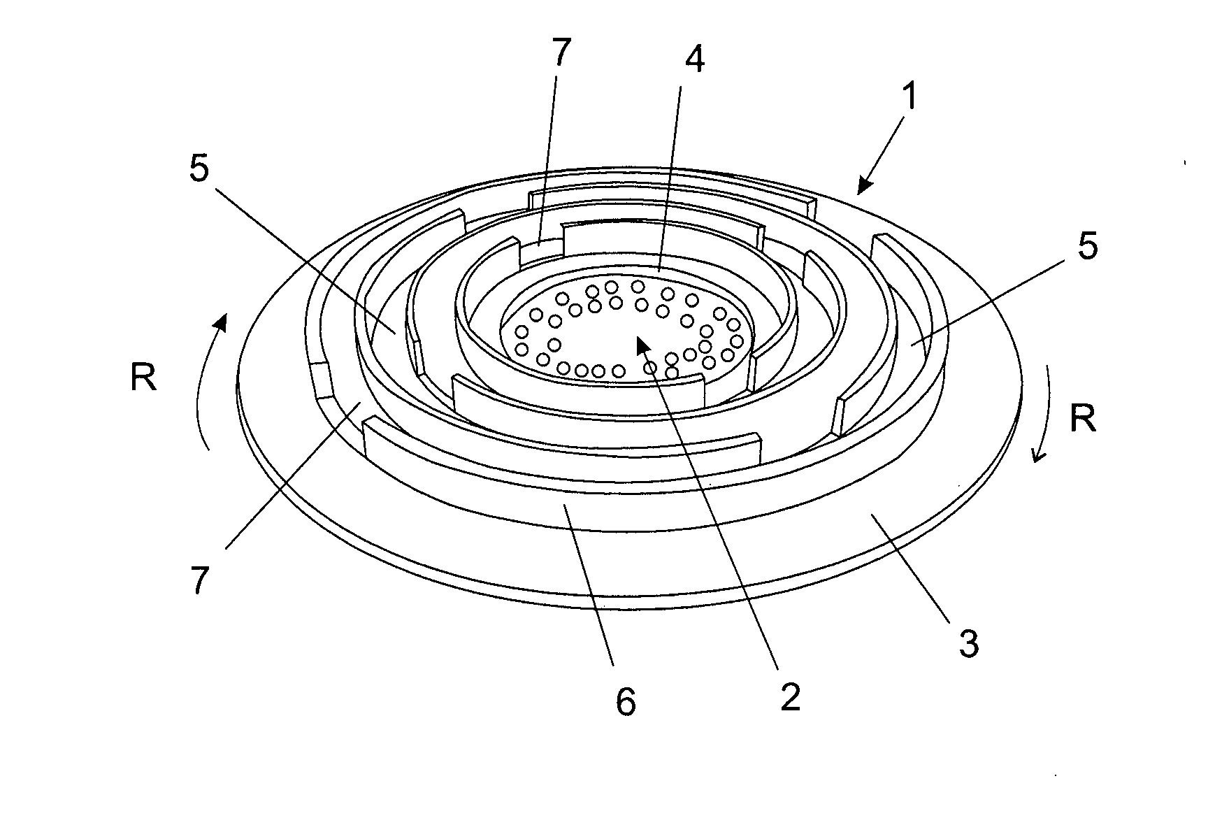
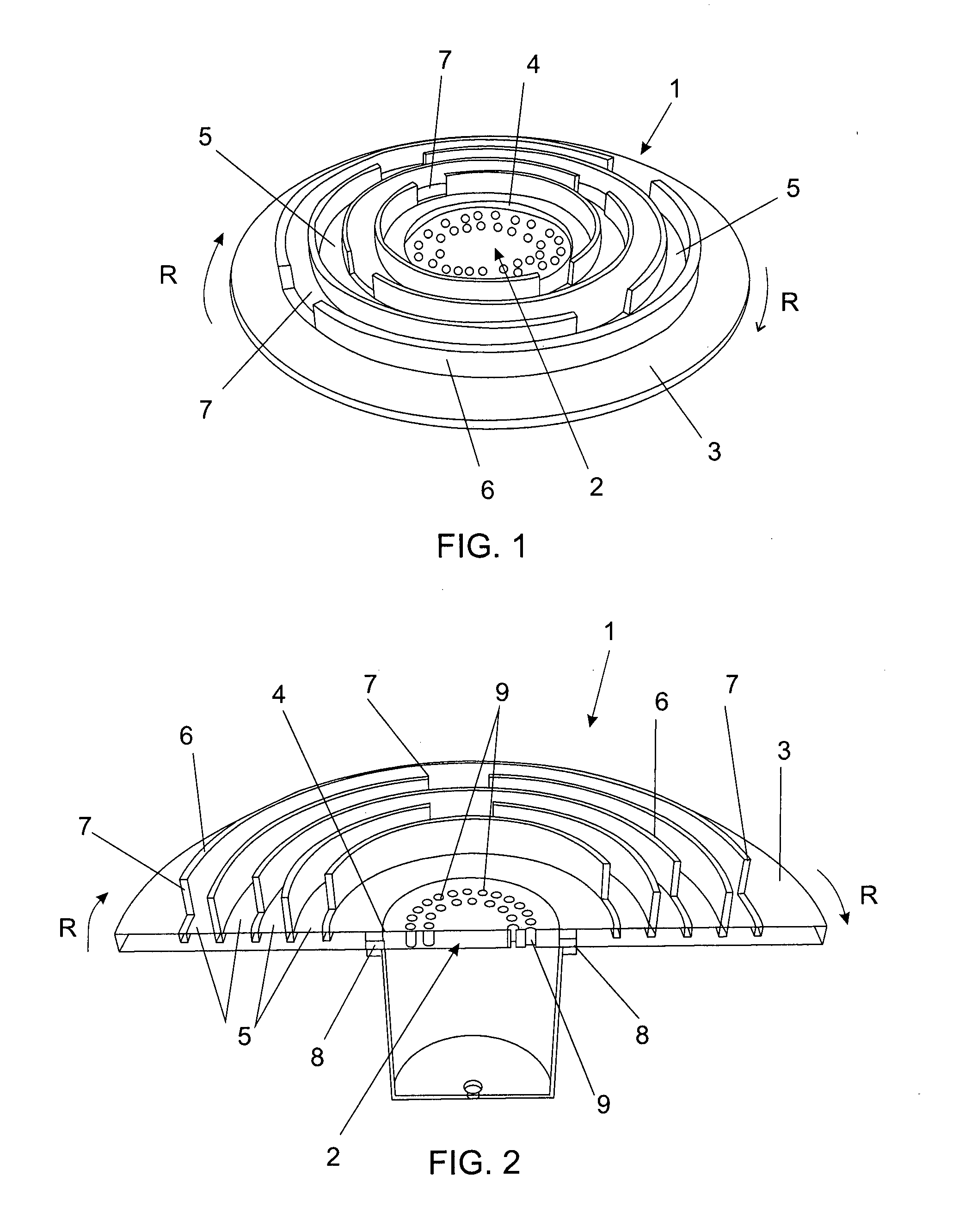
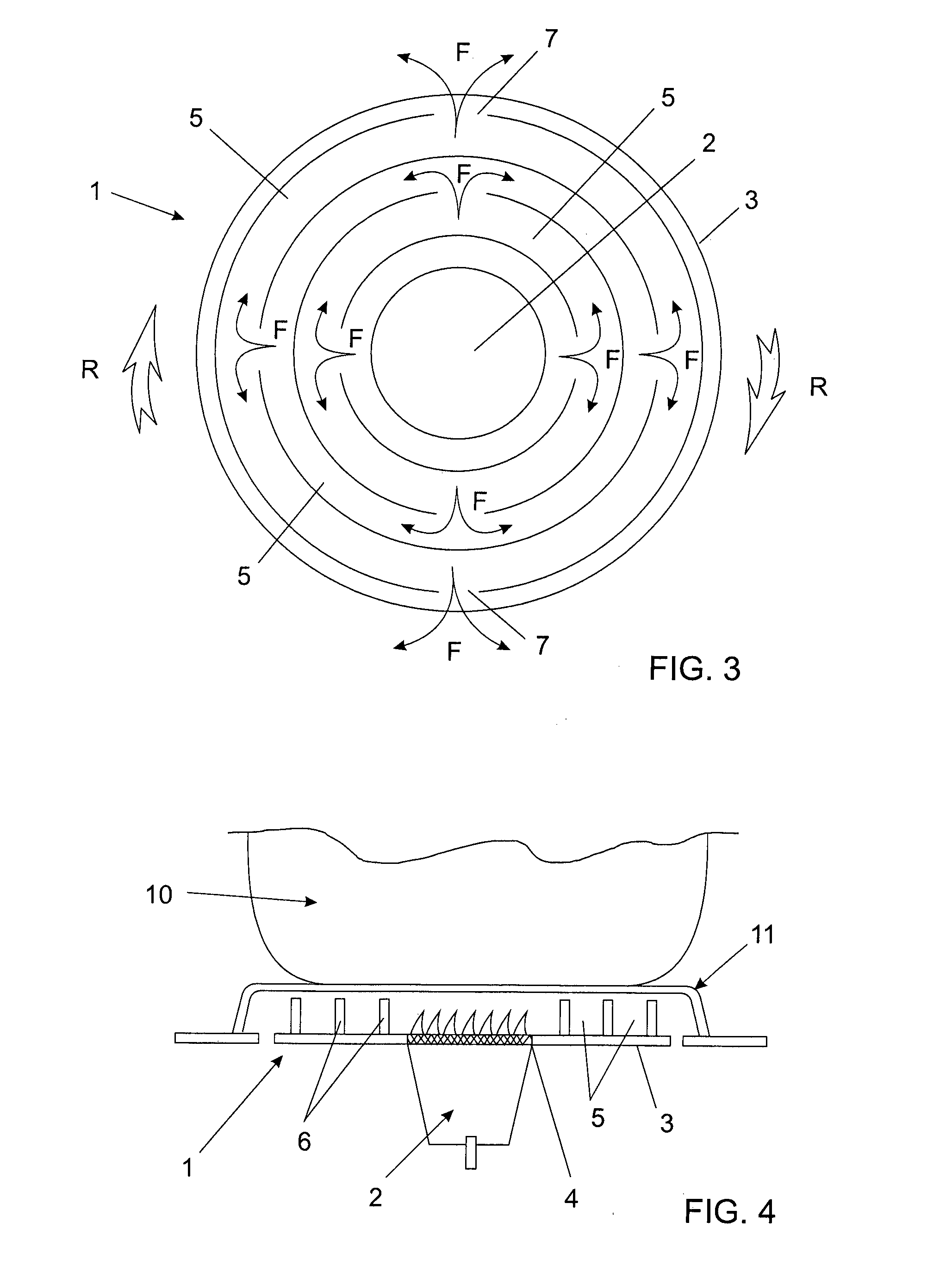
[0027]The gas flow directing device 1 of the present invention is an accessory that can be coupled with a burner 2 or alternatively it is possible that said burner comprises the directing device of the present invention. Thus, it is important to point out that said gas flow directing device can be either an entirely independent part of the burner or a part that constitutes the burner assembly of a cooking appliance.

[0028]In this sense, said gas flow directing device 1 comprises a base 3 comprising opening 4 for fitting it over the burner 2 wherein said base 3 is...


PUM


Abstract

The present invention refers to a gas flow directing device (1) for burners (2) of cooking appliances, comprising innovative technical and functional features capable of better using gases from combustion process. However, it is mainly directed to maximize the efficiency of heat exchange of burners with cooking utensils. More particularly, said gas flow directing device (1) of the present invention comprises a base (3) provided with opening (4) for fitting a burner (2), wherein said base (3) is arranged such that it can be freely rotated around the burner (2) and comprises at least a pathway (5) configured from the arrangement of at least one outwardly projected distribution wall (6) containing at least an opening (7).

Description

FIELD OF THE INVENTION[0001]The present invention refers to a gas flow directing device for burners of oven-type cooking appliances. More particularly, said gas flow directing device comprises innovative technical and functional features capable of better using gases from a combustion process, but mainly maximizing efficiency of heat exchange of burners with cooking utensils.[0002]More preferably, the present invention refers to a device to be used in cooking appliance burners having the ability to increase the residence time of hot gases under a utensil by means of reducing dissipation speed of said gases.BACKGROUND OF THE INVENTION[0003]As generally known by those skilled in the art, cooking appliances are used for heating cooking utensils, such as pans, dishes, frying pans, etc. To this effect, these appliances are provided with a series of burners over which said utensils for the preparations of food are disposed, wherein the configuration of said burners is intended to produce ...

Claims


Application Information

Patent Timeline
IPC IPC(8): F24C3/12F24C3/08F23D14/70
CPCF24C3/126F24C3/085F23D14/70F23D14/02F23D2900/14021Y02B40/00
Inventor FAVERI, RODRIGO FREGULIA DESILVA, MARCOS RAPHAEL DA
Owner WHIRPOOL SA
Why Eureka
Try Eureka