Milling equipment for milling two ends of rack

A rack and milling technology, which is applied in the direction of milling machine equipment, milling machine equipment details, metal processing equipment, etc., can solve the problems of complex clamping process, time-consuming, low efficiency and not suitable for large-scale end face processing, etc., to avoid repeated positioning , improve processing efficiency, and realize the effect of automatic positioning processing

Inactive Publication Date: 2014-07-16
徐州彭城塑业有限公司
View PDF7 Cites 5 Cited by
  • Summary
  • Abstract
  • Description
  • Claims
  • Application Information

AI Technical Summary

Problems solved by technology

[0002] After processing the toothed rack, the end faces of both ends need to be milled so that the length of the rack can meet the size requirements. The existing rack machining centers mostly use general-purpose machining centers. Due to the complicated clamping process, two Positioning the end face and processing the end face twice takes a lot of time, and the efficiency is low, so it is not suitable for large-scale end face processing

Method used


Image

  • Milling equipment for milling two ends of rack
  • Milling equipment for milling two ends of rack
  • Milling equipment for milling two ends of rack

Examples


Embodiment Construction

[0014] The present invention will be further described in detail below in conjunction with the accompanying drawings and examples. The following examples are explanations of the present invention and the present invention is not limited to the following examples.

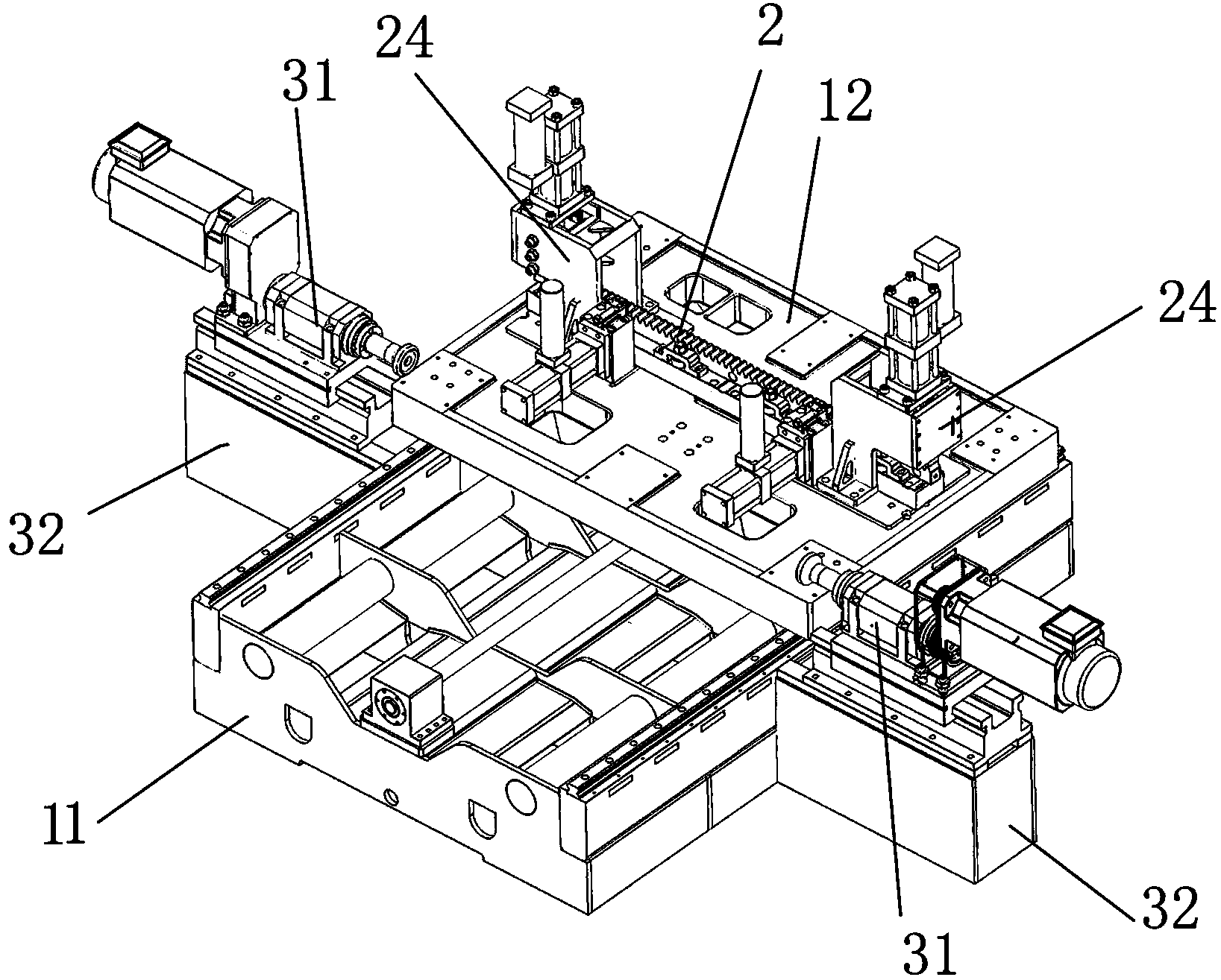
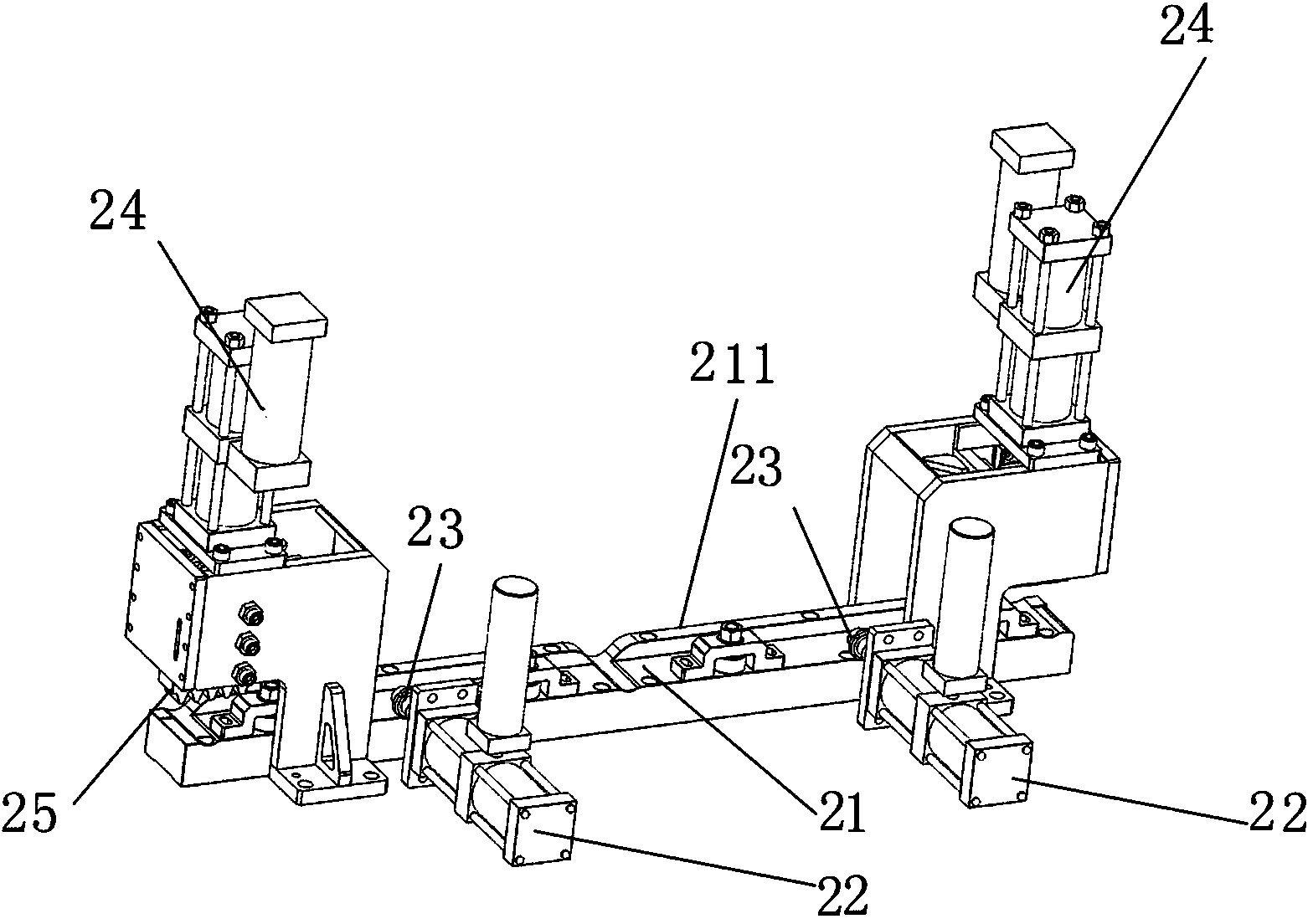
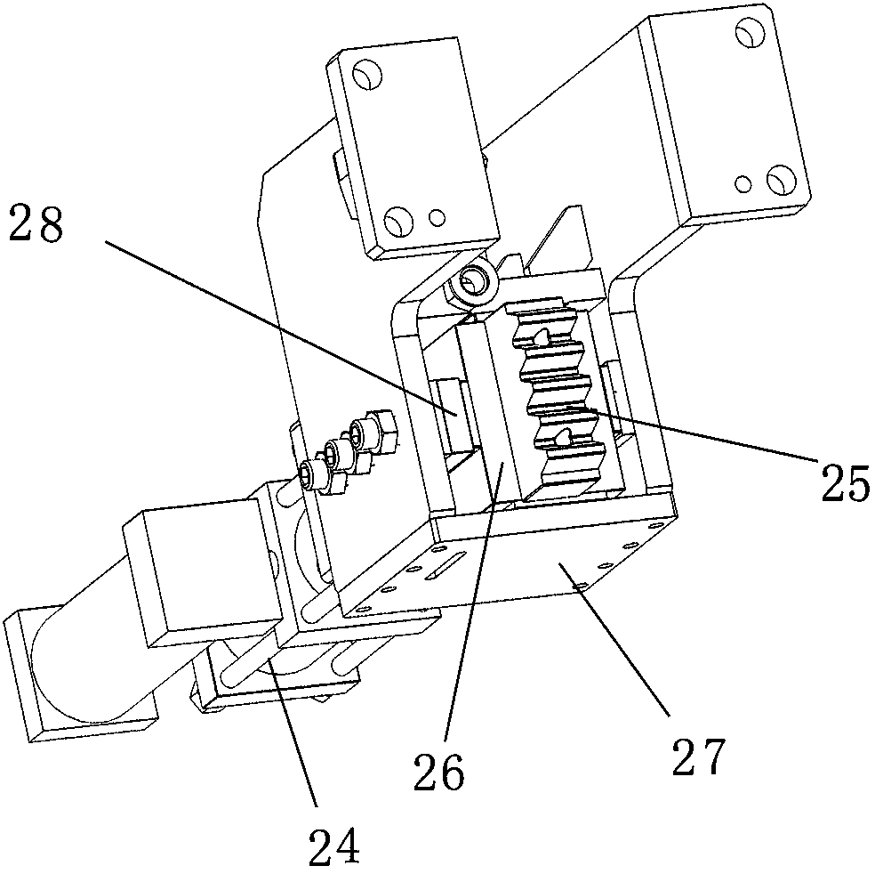
[0015] see Figure 1-Figure 3 , the present embodiment is used for the milling equipment of milling rack two ends, comprises workbench base 11, workbench 12, rack positioning structure 2 and first screw power head, and rack positioning structure 2 is arranged on the workbench 12, works The table 12 is slidably installed on the workbench base 11 through the moving guide rail. The first screw power head drives the workbench 12 to perform horizontal reciprocating linear motion relative to the workbench base 11. The rack positioning structure 2 includes a rack base 21, a rack fixed Pressure cylinder 22, rack fixed booster block 23, rack positioning booster cylinder 24 and rack positioning booster block 25, one side of r...


PUM


Abstract

The invention discloses milling equipment for milling two ends of a rack. The milling equipment is characterized by comprising a workbench base, a workbench, a rack positioning structure and a first screw rod power head, wherein the rack positioning structure comprises a rack base, a rack fixing pressurizing cylinder, a rack fixing pressurizing block, a rack positioning pressurizing cylinder and a rack positioning pressurizing block; two sides of the workbench base are respectively provided with end face processing power head bases, rack end face processing power heads are fixed onto the end face processing power head bases, and the end face processing power head bases are fixed on the workbench base; the feeding direction of the rack end face processing power heads is parallel to the length direction of the rack base. Compared with the prior art, the milling equipment has a simple and reasonable structure and reaches automatic positioning processing, two end faces simultaneously process, the repeated positioning is avoided, and the processing efficiency is improved.

Description

technical field [0001] The invention relates to a milling device for milling both ends of a rack. Background technique [0002] After processing the toothed rack, the end faces of both ends need to be milled so that the length of the rack can meet the size requirements. The existing rack machining centers mostly use general-purpose machining centers. Due to the complicated clamping process, two Positioning the end face and processing the end face twice takes a lot of time, and the low efficiency is not suitable for mass end face processing. Contents of the invention [0003] The object of the present invention is to overcome the above-mentioned shortcomings in the prior art, and provide a milling device for milling both ends of a rack with reasonable structural design, high processing efficiency and one-time clamping and processing. [0004] The technical solution adopted by the present invention to solve the above problems is: [0005] A milling device for milling both ...

Claims


Application Information

Patent Timeline
Patent Type & Authority Applications(China)
IPC IPC(8): B23C3/00B23C9/00B23Q3/08
Inventor 沈平高尔荣
Owner 徐州彭城塑业有限公司
Why Eureka
Try Eureka