Electric resistance welding micro-welding spot welding machine

A technology of resistance welding and welding points, which is applied in the field of micro-welding equipment, can solve the problems of inability to accurately control electrode force and less investment in manpower and material resources, and achieve the effects of avoiding hindering welding operations, improving verticality, and reducing losses or errors

Active Publication Date: 2014-07-16
GUANGZHOU MICRO WELDING EQUIP
View PDF10 Cites 25 Cited by
  • Summary
  • Abstract
  • Description
  • Claims
  • Application Information

AI Technical Summary

Problems solved by technology

Microscopic welding of resistance welding requires precise control of electrode force. As for how to precisely control electrode force, the spot welding machine implemented according to the technical solutions of the above listed patent announcements is either limited to the lack of theoretical basis or limited to the manpower to study it. The input of material resources is too little, and the existing technology cannot realize the precise control of electrode force in the true sense

Method used


Image

  • Electric resistance welding micro-welding spot welding machine
  • Electric resistance welding micro-welding spot welding machine
  • Electric resistance welding micro-welding spot welding machine

Examples


Embodiment Construction

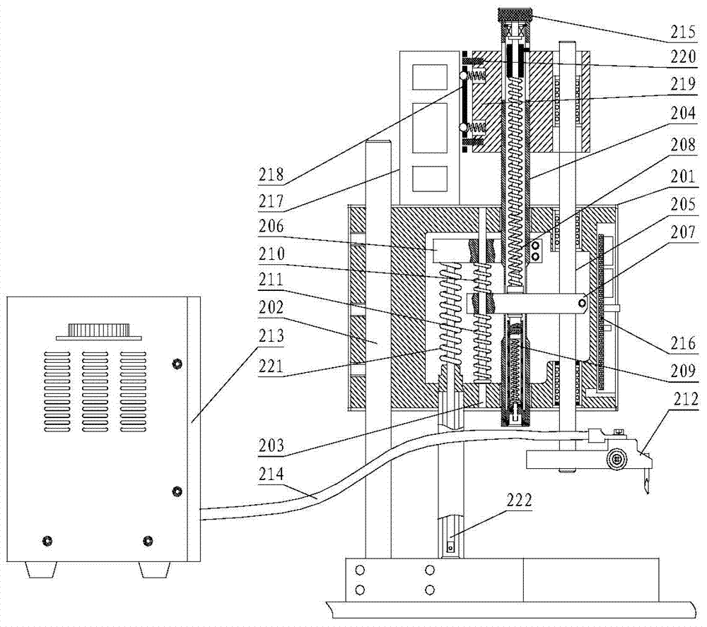
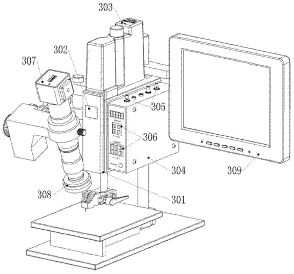
[0054] First of all, it needs to be understood that the concept of "resistance welding micro-welding" in the present invention is proposed for micro-workpieces that cannot be welded by resistance welding under direct vision. Resistance welding micro-welding not only needs to provide accurate electrode force and welding energy, Welding operations under micro-optical devices are also required. Due to space limitation, the present invention mainly introduces the head of the spot welding machine, the welding head clamp and the micro-optical device.

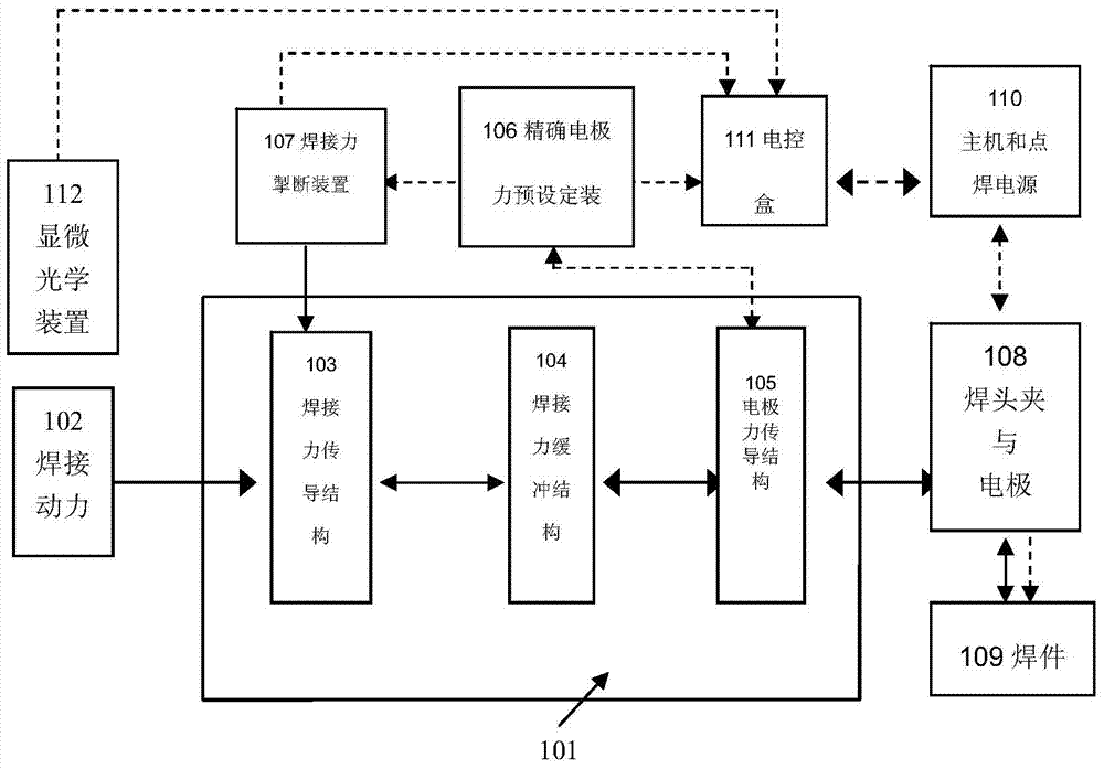
[0055] attached figure 1 Briefly introduce the general structural block diagram of the resistance welding microscopic welding spot welding machine of the present invention.

[0056] exist figure 1 Among them, the large box 101 represents the frame of the machine head, the small box 102 represents the welding power (welding force) provided by the external power source of the spot welder, 103 represents the welding force transmission ...


PUM


Abstract

The invention discloses an electric resistance welding micro-welding spot welding machine and mainly relates to noses. A mechatronics accurate electrode force pressurizing system is mounted on a nose frame, and electrode force is kept in a preset range and relatively constant during whole spot welding by the synergy and interaction of a welding acting force transmission device, an accurate electrode force presetting device and a welding force switching off device. A spot welding machine nose structure with an electric control box is provided, and nose feed and spot welding power supply output presetting are performed through the electric control box. A plastic nose frame and a stepped welding head clamp structure are provided to guarantee accurate torque transmission. A nose and a microscopy optical device are integrated, and the brand new electric resistance welding micro-welding spot welding machine is provided with the unique optical mechatronics spot welding machine nose.

Description

technical field [0001] The invention relates to a microscopic welding device, in particular to a resistance welding microscopic welding spot welder. Background technique [0002] The applicant has been engaged in the research and development of resistance micro-welding equipment for a long time, so he is familiar with various realization schemes of resistance welding equipment. Generally, resistance welding equipment is driven by a variety of welding power sources. For the head of a spot welding machine, only the structure of a pressure mechanism or an electrode grip is generally proposed. The structure is relatively simple, and there is still room for improvement. The applicant has successively held the following patents related to spot welding equipment: [0003] 1. Invention name: spot welding machine that can directly weld enameled wire, announcement number: CN1318449, announcement date: October 24, 2001; [0004] 2. Invention name: spot welding machine head with press...

Claims


Application Information

Patent Timeline
Patent Type & Authority Applications(China)
IPC IPC(8): B23K11/11B23K11/31B23K11/36
CPCB23K11/11B23K11/25B23K11/31B23K11/36B23K11/115B23K11/315B23K11/318
Inventor 杨仕桐
Owner GUANGZHOU MICRO WELDING EQUIP
Why Eureka
Try Eureka