Automatic assembling tool for impeller box and centre of water meter movement

An automatic assembly and top-notch technology, applied in metal processing, manufacturing tools, metal processing equipment, etc., can solve the problems of low degree of automation, poor assembly quality and uniformity, difficult to control the pressure, etc., to achieve reliable and uniform quality, improve The effect of assembly efficiency

Active Publication Date: 2014-07-16
超仪科技股份有限公司
View PDF11 Cites 19 Cited by
  • Summary
  • Abstract
  • Description
  • Claims
  • Application Information

AI Technical Summary

Problems solved by technology

[0004] At present, the tip is usually manually pressed into the installation hole at the bottom of the impeller box. This installation method has the following disadvantages: firstly, it is difficult to grasp the magnitude of the pressure applied by hand, and it is difficult to control the depth of the tip; the direction of the pressure applied by hand is not accurate. , which may lead to deviations in the position of the top; therefore, the final assembly quality and assembly uniformity are poor. Secondly, it is inconvenient for workers to operate, labor-intensive, and easily injured; finally, due to the low degree of automation, the overall work efficiency Low, the work efficiency of skilled workers is difficult to break through the limit
Although this patent solves the automatic assembly process of the tip and the impeller box, the setting of the impeller box and the tip on the positioning mechanism before assembly and the output of the impeller box after assembly still need to be completed by manual operation, which is not fully automated. further improvement

Method used


Image

  • Automatic assembling tool for impeller box and centre of water meter movement
  • Automatic assembling tool for impeller box and centre of water meter movement
  • Automatic assembling tool for impeller box and centre of water meter movement

Examples


Embodiment Construction

[0055] The present invention will be further described in detail below in conjunction with the accompanying drawings and embodiments.

[0056] Such as Figure 12 , Figure 13 and Figure 14 As shown, the leaf hinge 10 in the prior art is composed of three parts, namely the port part 1a, the lower end part 1c and the convex ring part 1b between the port part 1a and the lower end part 1c, wherein the diameter of the port part 1a is larger than The lower end 1c has a diameter, and the inner wall of the lower end 1c has a shaft hole 1d for setting the tip 10a. One end of the tip 10a forms a tip, and the other end is fitted in the shaft hole 1d of the leaf hinge.

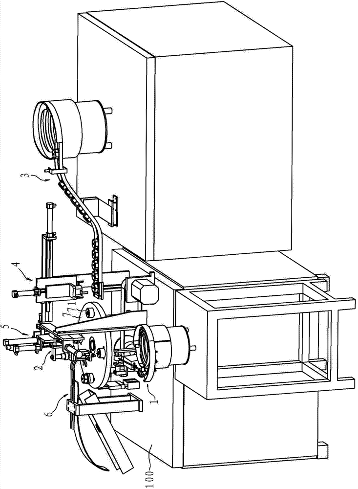
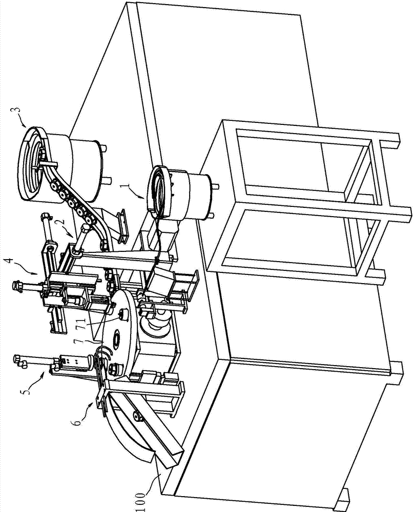
[0057] Such as figure 1 and figure 2 As shown, the water meter core leaf and top automatic assembly tooling in this embodiment includes a rotating disk 7, a top vibration output mechanism 1, a top clamping mechanism 2, a leaf hinge vibration output mechanism 3, a leaf hinge clamping mechanism 4, and a rotating disk...


PUM


Abstract

The invention provides an automatic assembling tool for an impeller box and a centre of a water meter movement. The automatic assembling tool is characterized by comprising a rotating plate, a centre vibration output mechanism, a centre clamping and taking mechanism, an impeller box vibration output mechanism, an impeller box clamping and taking mechanism, a clamping mechanism and an impeller box discharge mechanism. The rotating plate can rotate in a gap mode under driving of a motor. The upper end face of the rotating plate is at least provided with four installation bases for impeller boxes to cover in the circumferential direction. The middle of each installation base is provided with a vertical channel for a centre to be inserted. The impeller box discharge mechanism can unload the assembled impeller boxes from the installation bases. The centre clamping and taking mechanism, the impeller box clamping and taking mechanism, the clamping mechanism and the impeller box discharge mechanism are sequentially arranged around the rotating plate. Compared with the prior art, the automatic assembling tool has the advantages that an automatic machine structure is adopted, manual operation can be completely replaced, and therefore the assembling efficiency is greatly improved, and the quality of the assembled products is reliable and uniform.

Description

technical field [0001] The invention relates to automatic assembly equipment for water meters, in particular to automatic assembly tooling for leaf hinges and tips. It belongs to the technical field of water meter processing. Background technique [0002] The rotor-type water meter is a kind of speed-type water meter, which is widely used in the world. The metering mechanism of the rotor-type water meter is mainly composed of a gear box, an impeller box (also known as a leaf joint), an integral impeller, a top, and an adjustment plate, among which the gear box and the impeller box form the movement. The metering mechanism plays a key role in the metering performance and durability of the water meter. [0003] Patent No. ZL200710035843.5 Chinese Invention Patent "A Rotary Wing Water Meter" (authorized announcement No. CN100529681C) China discloses a water meter, its structure: the tip is installed at the center of the bottom of the impeller box, at the bottom of the impelle...

Claims


Application Information

Patent Timeline
Patent Type & Authority Applications(China)
IPC IPC(8): B23P19/027
CPCB23P19/001B23P19/007B23P19/027
Inventor 赵如松敖开才
Owner 超仪科技股份有限公司
Why Eureka
Try Eureka