Infrared Suppressor and Its Infrared Suppression Method for Exhaust System of Helicopter Turboshaft Engine

A turboshaft engine, infrared suppression technology, applied in the direction of machines/engines, engine components, exhaust devices, etc., can solve the problem of difficulty in the influence of infrared radiation of engine exhaust devices, and achieve the purpose of reducing exhaust temperature, reducing infrared radiation, reducing The effect of low temperature

Inactive Publication Date: 2016-03-02
NANJING UNIV OF AERONAUTICS & ASTRONAUTICS
View PDF2 Cites 3 Cited by
  • Summary
  • Abstract
  • Description
  • Claims
  • Application Information

AI Technical Summary

Problems solved by technology

The second-generation infrared suppressor is still an add-on or optional part of the engine, and its shape and size are too restricted. Although it reduces the temperature of hot parts and exhaust exhaust to a certain extent, it is necessary to reduce the temperature by 3~ The infrared radiation feature in the 5μm band has a significant effect, but compared to the fuselage, its exposed shield and exhaust tail flame are still high-temperature hotspots displayed by point sources, and it is very difficult to further eliminate the infrared radiation influence of the engine exhaust device
It can be said that this integrated structure of helicopter exhaust system and fuselage is a new concept of stealth structure. At present, our understanding of its complex aerodynamic layout mechanism and infrared stealth effect is almost blank.

Method used


Image

  • Infrared Suppressor and Its Infrared Suppression Method for Exhaust System of Helicopter Turboshaft Engine
  • Infrared Suppressor and Its Infrared Suppression Method for Exhaust System of Helicopter Turboshaft Engine
  • Infrared Suppressor and Its Infrared Suppression Method for Exhaust System of Helicopter Turboshaft Engine

Examples


Embodiment Construction

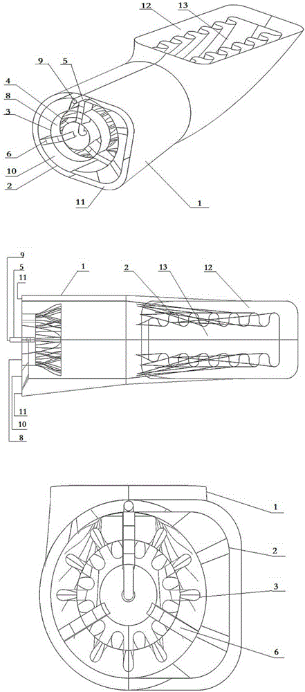
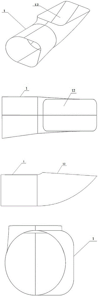
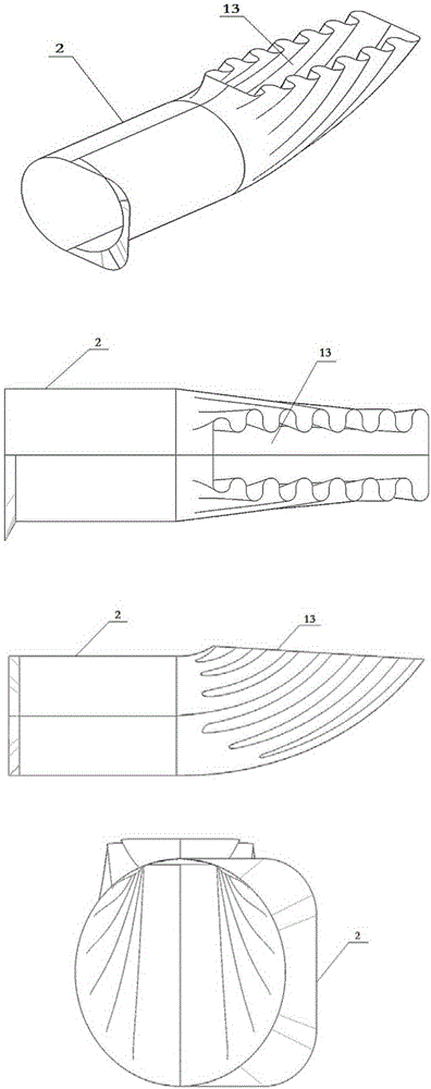
[0032] Please refer to Figure 1 to Figure 10 As shown, the infrared suppressor of the helicopter turboshaft engine exhaust system of the present invention consists of a binary curved fairing 1, a binary curved lobe injection mixing tube 2, a first-stage circular row of wave lobe nozzles 3, an exhaust inner cone 4, Sand control residual air conduit 5 and hollow support plate 6 are formed. One side of the three hollow support plates 6 is connected to the wall surface of the exhaust inner cone 4 by welding, the sand control residual gas inlet 9 and the sand control residual gas outlet 14 are arranged on the sand control residual gas conduit 5, and the sand control residual gas conduit 5 is penetrated In one of the hollow support plates 6, it is further connected with the hollow support plate 6, and the sand control residual air inlet of the sand control residual air conduit 5 extends out of the hollow support plate 6 and the outer side of the exhaust inner cone 4, and the sand c...


PUM


Abstract

The invention provides an infrared suppressor and an infrared suppression method for an exhaust system of a turboshaft engine of a helicopter and belongs to the technical field of design of the exhaust system of the turboshaft engine of the helicopter and infrared suppression. The infrared suppressor of the exhaust system of the turboshaft engine of the helicopter comprises a binary bending fairing cover, a binary bending wave lobe injection mixing tube, primary circularly-arranged lobe spray pipes, an exhaust inner cone, a sand prevention residual air guide pipe and a hollow support plate. On one hand, sand prevention residual air is guided into the exhaust inner cone and is directly mixed with high-temperature exhaust core stream behind an engine turbine, and exhaust core temperature is greatly lowered; on the other hand, environmental cold air sucked by exhaust momentum behind the engine turbine is mixed with hot exhaust air, low exhaust temperature is further lowered, convection is formed in the binary bending fairing cover of the infrared suppressor, and the temperature of exposed surface of the infrared suppressor is greatly lowered. Exhaust wake flame and infrared radiation on the surface of the infrared suppressor are lowered to the greatest extent.

Description

Technical field: [0001] The invention relates to an infrared suppressor for an exhaust system of a helicopter turboshaft engine and an infrared suppression method thereof, and belongs to the technical field of exhaust system design and infrared suppression of a helicopter turboshaft engine. Background technique: [0002] (1). Infrared suppression background of turboshaft engine exhaust system: [0003] In modern warfare, military helicopters are playing an increasingly important role in local combat areas, especially those with harsh geographical conditions. Many countries in the world have developed and strengthened helicopters as an important component of air power. . With the application of infrared detection and tracking technology in the military, a large number of infrared guided weapons have appeared, which has caused a great threat to the survivability of armed helicopters with thermal power devices in the war environment. An important combat technical indicator of...

Claims


Application Information

Patent Timeline
Patent Type & Authority Patents(China)
IPC IPC(8): F01N3/02
Inventor 谭晓茗陈庚单勇张靖周
Owner NANJING UNIV OF AERONAUTICS & ASTRONAUTICS
Why Eureka
Try Eureka