Laser damage resistance testing system

A test system and anti-damage technology, applied in the direction of testing optical properties, etc., can solve the problems such as the inability to effectively and accurately judge the damage resistance of the sample, the single judgment method, and the inability to change the power.

Inactive Publication Date: 2014-07-16
11TH RES INST OF CHINA ELECTRONICS TECH GROUP CORP
View PDF4 Cites 21 Cited by
  • Summary
  • Abstract
  • Description
  • Claims
  • Application Information

AI Technical Summary

Problems solved by technology

[0003] In the existing anti-damage testing devices, it is usually judged whether it constitutes damage by applying a certain power to the surface of the sample, but usually the power cannot be changed, and the judgment method is single, resulting in the inability to effectively and accurately judge the damage resistance of the sample

Method used


Image

  • Laser damage resistance testing system

Examples


Embodiment 1

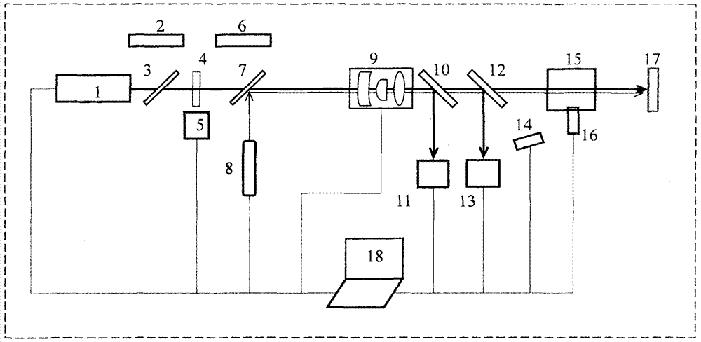
[0020] The laser damage resistance testing system includes: pulse laser 1, first light baffle plate 2, first polarizer 3, first 1 / 2 wave plate 4, first electric control rotary table 5, second light baffle plate 6, second polarizer 7. Indicating light source 8, electronically controlled zoom system 9, first 45° partial reflector 10, CCD spot analyzer 11, second 45° partial reflector 12, energy meter 13, photoelectric detector 14, lofting room 15, monitoring Camera 16, third light barrier 17, control system 18.

[0021] The connections between the components are:

[0022] Along the direction of the optical axis, the following components are arranged in sequence: pulsed laser 1, first polarizer 3, 1 / 2 wave plate 4, second polarizer 7, electronically controlled zoom system 9, first 45° partial reflector 10, second polarizer Two 45° partial reflector 12, lofting room 15, monitoring camera 16, third light blocking plate 17;

[0023] The first electronically controlled rotary table...

Embodiment 2

[0043] Other structures are the same as in Embodiment 1, and the anti-damage testing system also includes a second 1 / 2 wave plate 19, and a second electrically controlled rotary table 20, that is, there are two 1 / 2 wave plates between the pulse laser and the electronically controlled zoom system. The distribution of the wave plate and two polarizers along the optical axis is:

[0044] The pulse laser, the second 1 / 2 wave plate 19, the first polarizer 3, the first 1 / 2 wave plate 4, the second polarizer 7, and the electronically controlled zoom system 9 are arranged in the direction of the optical axis in sequence, and other components and their arrangement Same as in the first embodiment. The second electronically controlled rotating stage 20 controls the rotation angle of the second 1 / 2 wave plate 19 .

[0045] This structure can effectively fine-tune the output power of the laser, so that the laser power density of the final spot can reach about 0-100MW / cm 2 , 0-200MW / cm 2...


PUM


Abstract

The invention provides a laser damage resistance testing system which comprises a pulse laser, a first light barrier, a first polaroid, a first half wave plate, a first electronic control rotating table, a second light barrier, a second polaroid, an indicating light source, an electronic control zoom system, a first 45-degree partial reflecting mirror, a CCD facula analysis meter, a second 45-degree partial reflecting mirror, an energy meter, a photoelectric detector, a sample room, a monitoring camera, a third light barrier and a control system. Lasers are focused in the sample room, focused faculae can be adjusted continually through the control system, damage strength is formed, video real-time monitoring is available in the sample room so that a tester can monitor a threshold value point when a sample is damaged, the size of the faculae at the position of the sample is monitored in real time by the CCD facula analysis meter, a three-dimensional strength distribution diagram of the faculae is given, pulse energy is monitored in real time by the energy meter, the pulse width of the lasers is detected by the photoelectric detector in real time, real-time peak value power density is provided after detection data are processed through software, and the damage threshold value of the sample is detected accurately.

Description

Technical field: [0001] The invention relates to a laser testing system, in particular to a laser damage resistance testing system. Background technique: [0002] In recent years, due to the tremendous development of lasers, they have been gradually applied in more and more fields, among which high-power lasers have been widely used in particular. In lasers, due to the high energy of the beam, the internal components of the system, such as resonator mirrors, lenses, beam splitters, etc. The production and operation of the laser are closely related. When any one of the components is damaged, the quality of the laser beam will be reduced, the output power will be reduced, and the laser will even fail to operate. In some application fields, such as laser marking, welding and scanning, etc., when the output power of the laser is too high, the processed sample will be damaged. Therefore, it is also necessary to monitor the laser damage of the workpiece to determine the appropria...

Claims


Application Information

Patent Timeline
Patent Type & Authority Applications(China)
IPC IPC(8): G01M11/02
Inventor 苑利钢陈国侯天禹韩隆周寿桓赵鸿王克强
Owner 11TH RES INST OF CHINA ELECTRONICS TECH GROUP CORP
Why Eureka
Try Eureka