
Processing box

A process box and outlet technology, applied in the field of process boxes, can solve the problems of large contact force on the electrical contact portion 181, unfavorable cleaning of contaminants, increased use costs for users, etc., to improve electrical connection stability and electrical connection fault tolerance. performance, improve the fault tolerance of electrical connections, and protect the effect of electrical connection structures

Inactive Publication Date: 2014-07-16
PRINT RITE UNICORN IMAGE PROD CO LTD
View PDF1 Cites 17 Cited by
  • Summary
  • Abstract
  • Description
  • Claims
  • Application Information

AI Technical Summary

Problems solved by technology

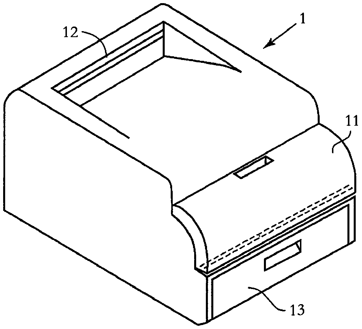
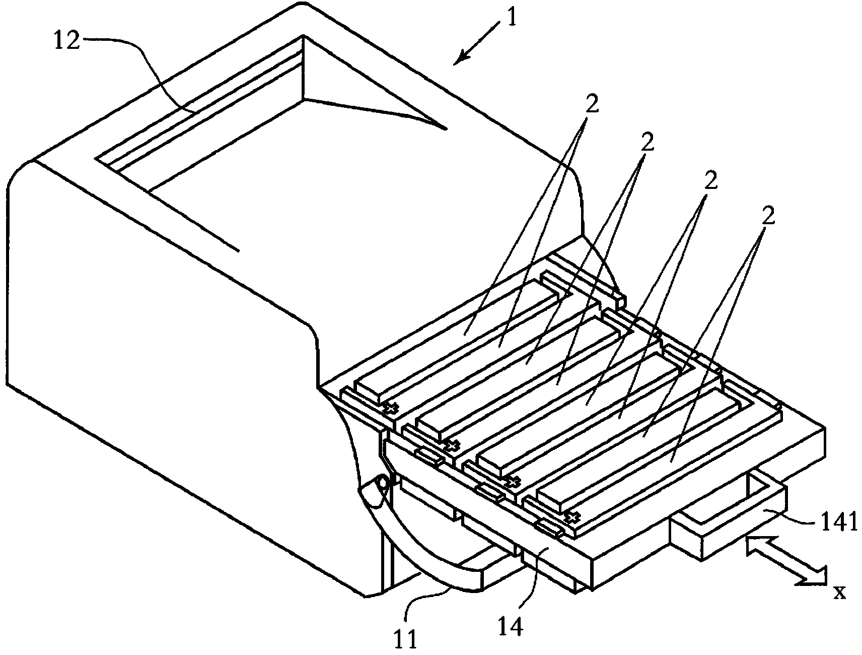
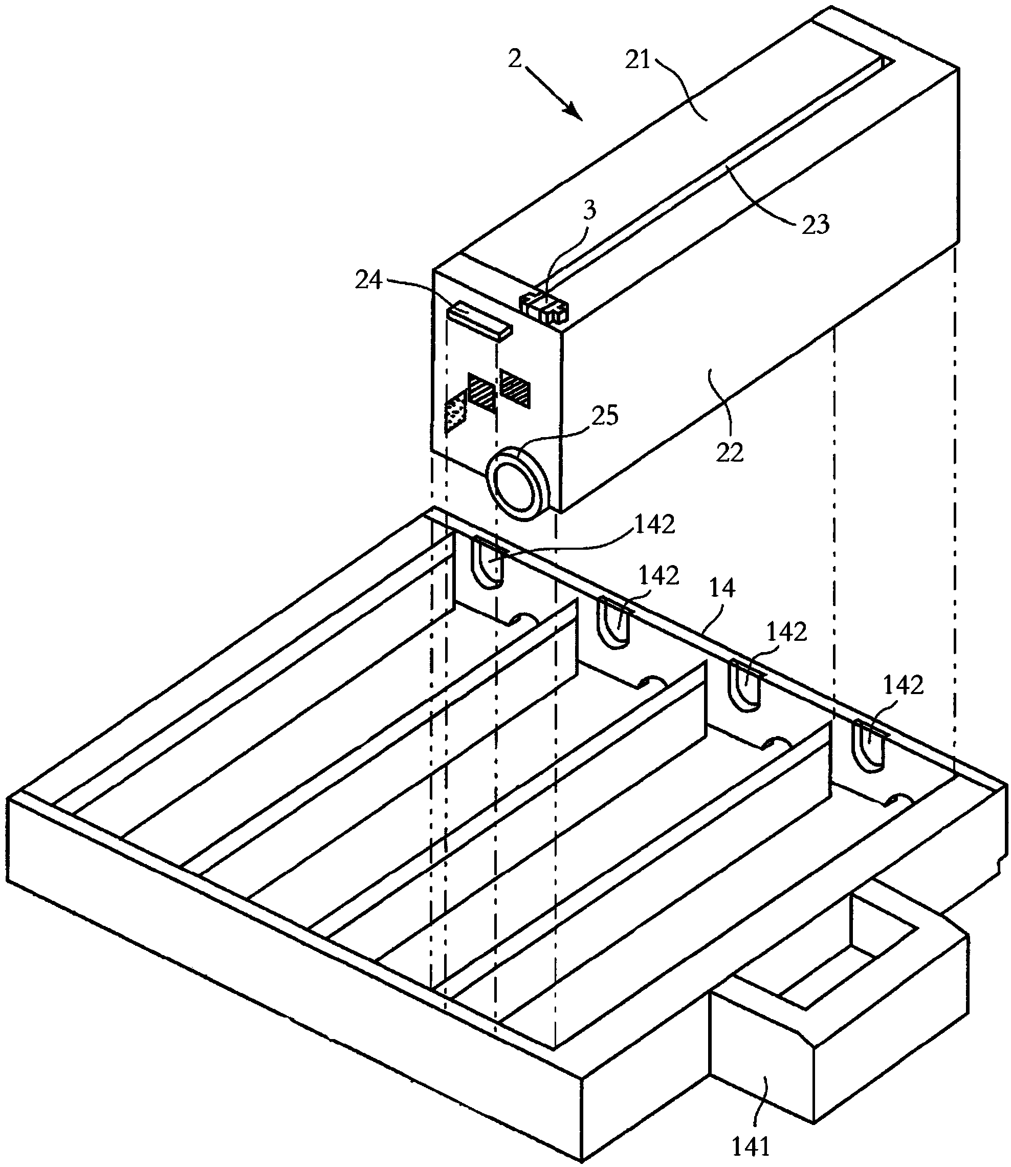
[0011] However, from image 3 and Figure 4 It can be seen that the chip 3 of consumables is installed on the outer wall above the process box 2 in a horizontal manner, and the electrical connection part 32 is also arranged horizontally. After the bracket 14 is installed, extremely fine carbon powder or fine dust are easy to float from the process box 2 to the outside of the process box 2 from the gap 23, and fall on the electrical connection portion 32, thereby causing the pollution of the electrical connection portion 32, Thereby seriously affecting the electrical connection performance of the electrical connection part 32
At the same time, since the consumable chip 3 placed horizontally is not conducive to the cleaning of pollutants, when the pollutants accumulate more and more, the pollutants on the consumable chip 3 cannot be cleaned well by the electric contact part 181 alone. , resulting in the failure of the electrical connection between the consumable chip 3 and the laser printer 1, resulting in failure to work normally
[0012] At the same time, refer to Figure 5 , the electrical connection between the electric contact part 181 and the consumable chip 3 depends on the mutual positioning of the positioning rib and the positioning groove. Due to the poor tolerance of the positioning rib and the positioning groove, after the laser printer 1 has been used for a long time, such as some parts If loss occurs, the positioning ribs and positioning grooves cannot be fixed with each other, resulting in electrical connection failure
[0013] refer to Image 6 Since the electric contact part 181 vertically squeezes the electric contact 321 of the consumable chip 3, the contact area between the electric contact part 181 and the electric contact 321 is small, which in turn causes the contact force of the electric contact part 181 to be relatively large, which is easy to Causes breakage or deformation of the electric contact part, and requires professionals to repair or replace the electric contact part after it is damaged, which causes a lot of inconvenience to the user and increases the cost of use for the user

Method used


Image

  • Processing box
  • Processing box
  • Processing box

Examples


Embodiment Construction

[0044] refer to Figure 7 with Figure 8 , the process box 4 includes a developing unit 41 and a drum unit 42, the developing unit 41 is installed on one side of the drum unit 42, the developing unit 42 casing surrounds a powder bin containing carbon powder, and a developing unit is provided at the opening of the powder bin. rollers (not shown). The shell of the drum unit 42 surrounds a waste toner bin containing waste toner, a photosensitive drum (not shown) is arranged at the opening of the waste toner bin, and a drive assembly 53 is installed at the end of the photosensitive drum. The drive assembly 53 includes a mounting part 532, three protrusions 531 of non-twisted shape are formed in the axial direction on the mounting part 532, and the three protrusions 531 are evenly arranged on the outer end of the mounting part 532 along the circumferential direction, and the driving assembly 53 is used for Receiving external rotational driving force, the photosensitive drum and d...


PUM


Abstract

The invention provides a processing box. The processing box comprises a developing unit and a drum unit, wherein a shell of the developing unit defines a powder cabin for storing carbon powder, a shell of the drum unit defines form a waste powder cabin for storing the waste powder, a developing roll is installed in an outlet of the powder cabin in a rotating manner, a photosensitive drum is installed in an outlet of the waste powder cabin in the rotating manner, one end of the photosensitive drum or the developing roll is provided with a driving assembly, the driving assembly comprises an installation part, a projection is arranged on the installation part, the driving assembly is installed on the first side wall of the shell in the rotating manner, a consumable chip is installed on the second side wall which is opposite to the first side wall, the consumable chip comprises a substrate, an electronic module which is arranged on the substrate and an electric connection part which is electrically connected with the electronic module, and the electric connection part is obliquely arranged on the substrate in the direction which is opposite to the first side wall. By adopting the processing box, the electric connection stability and the electric connection fault tolerance can be improved, the electric connection structure of the laser printer and the processing box is also effectively protected, and the durability of the laser printer and the processing box can be improved.

Description

technical field [0001] The invention relates to the field of printing consumables, in particular to a processing box. Background technique [0002] Image imaging equipment is a device that uses the principle of electrophotographic imaging to form images on recording materials. Image imaging equipment includes copiers, printers, fax machines, and the like. Process cartridges used in image forming equipment are generally divided into two types, one is an integral process cartridge including a developing roller as a developing device and a photosensitive drum, and the other is a split process cartridge that separates the photosensitive drum to the outside. Both process cartridges are detachably mounted into the main body of the image forming apparatus. [0003] A typical image imaging device is a laser printer. Laser printers are one of the most widely used image imaging devices at present. Laser printers use the physical and chemical principles of light, electricity, and heat...

Claims


Application Information

Patent Timeline
Patent Type & Authority Applications(China)
IPC IPC(8): G03G21/18
CPCG03G21/18
Inventor 苏健强何永刚
Owner PRINT RITE UNICORN IMAGE PROD CO LTD
Learn More