Frequency calibration method and device

A frequency calibration and variance technology, applied in the field of frequency calibration methods and devices, can solve the problems of increased processing delay, difficulty in setting the threshold of peak validity, uncertain delay, etc.

Active Publication Date: 2014-07-16
DATANG MOBILE COMM EQUIP CO LTD
3 Cites 17 Cited by

AI-Extracted Technical Summary

Problems solved by technology

In this way, on the one hand, it is difficult to set the threshold when judging the validity of the peak value. On the other hand, since it is necessary to search for a large frequency offset according to a certain step size, the processing delay will also be increased and there are factors of delay uncertainty.
[0007] It can be seen that the frequency offset estimation algorithm in the AFC calibration of the existing comprehensive tester under the modulation signal mode has a contradiction between a la...

Method used

The embodiment of the present invention provides a kind of frequency calibration method and device, makes terminal send PSK modulated signal, after receiving PSK modulated signal, intercept a section of data long enough after rising edge position, determine a group of data with minimum variance of amplitude Carry out coarse frequency offset estimation and coarse frequency offset compensation, then determine a more accurate time slot start position, re-intercept the data of a time slot, and determine the fine frequency offset offset value according to the data, so as to obtain a more accurate frequency offset offset, according to The frequency offset offset can be used for frequency calibration to improve the accuracy of frequency calibration. At the same time, since the coarse frequency offset estimation and coarse frequency offset compensation are performed first, the more accurate starting position of the time slot is determined, and the data is intercepted for fine frequency offset compensation. Therefore, the efficiency of determining the frequency offset offset value is improved, thereby improving the efficiency of frequency calibration.
Visible, owing to carry out coarse frequency deviation estimation and coarse frequency deviation compensation first, after determining more accurate time slot starting position again, intercept the data of a time slot and...

Abstract

The invention relates to the communication technology and discloses a frequency calibration method and device. A terminal sends a PSK modulation signal, after the PSK modulation signal is received, a section of data long enough behind the position of the rising edge is intercepted, a group of data are determined for rough frequency offset estimation and rough frequency offset compensation, wherein variance of the amplitude of the data is the smallest, then the precise time slot starting position is determined, data of a time slot are intercepted again, and a fine frequency offset deviant is determined according to the data, so that the accurate frequency offset is obtained, and accuracy of frequency calibration can be improved by conducting frequency calibration according to the frequency offset. Meanwhile, due to the fact that rough frequency offset estimation and rough frequency offset compensation are first conducted, then the precise time slot starting position is determined, and the data are intercepted for fine frequency offset compensation, efficiency for determining the frequency offset deviant is improved, and efficiency of frequency calibration is further improved.

Application Domain

Multi-frequency code systems

Technology Topic

Frequency offsetComputer science

Image

  • Frequency calibration method and device
  • Frequency calibration method and device
  • Frequency calibration method and device

Examples

  • Experimental program(2)

Example Embodiment

[0120] Example one
[0121] This embodiment is the frequency calibration during the AFC calibration in the modulated signal mode in the WCDMA system.
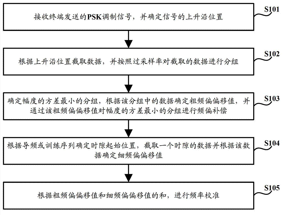
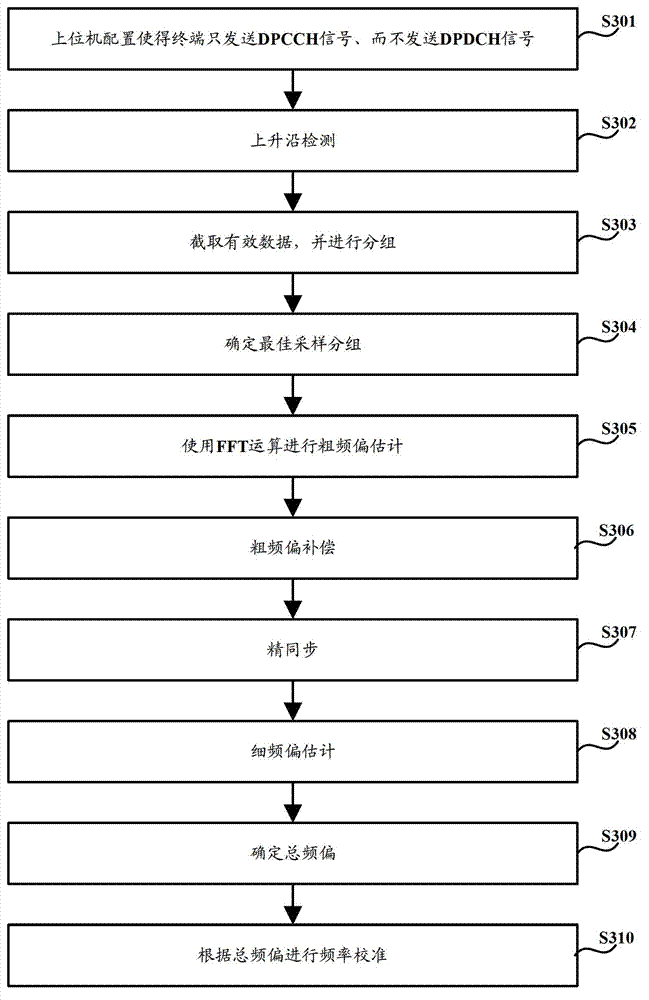
[0122] Such as image 3 As shown, the frequency calibration method includes:
[0123] Step S301, host computer configuration β c =15 and β d =0, so that the terminal only sends DPCCH signals, but not DPDCH signals. The purpose of this configuration is to obtain the modulation signal of the standard QPSK constellation, so as to facilitate the removal of modulation information, thereby performing frequency offset estimation.
[0124] Step S302, rising edge detection:
[0125] Suppose that the comprehensive tester receives a wireless frame of data r=[r(0), r(1),...,r(N-1)], N=OSR*N c *N slot , Where OSR is the oversampling rate, N c = 2560 is the number of chips in one slot of the DPCCH channel, N slot =15 is the number of time slots of input data;
[0126] Calculate the power value of the sliding window of the received signal sample point: P win ( i ) = X n = i i + L win - 1 | r ( n ) | 2 , i = 0,1 , . . . , N - L win ; Where L win The number of samples included in the power calculation window length.
[0127] Search rising edge:
[0128] for i = 0 : N - L win if P win ( i + L win ) P win ( i ) P lim I start = i + 2 L win end break ; end ;
[0129] Where P lim Is the rising edge power difference threshold.
[0130] If the received signal power value is known, the condition of the rising edge judgment can also be the absolute value of the power.
[0131] Step S303, intercept valid data, and perform grouping:
[0132] Take out the data used for coarse frequency offset estimation:
[0133] r′=[r′(0), r′(1),...,r′(N′-1)], N′=OSR*SF dpcch *N FOE ,
[0134] Where r′(i)=r(i+I start +N Δ *OSR), N Δ It is the margin set to ensure that the data after the actual data start position can be obtained, N FOE ≤N c Is the number of symbols used for frequency offset estimation, N c It is the number of chips in a slot (2560 for WCDMA and 864 for TD-SCDMA).
[0135] Data grouping:
[0136] The first N of r′ var *OSR data are grouped to get 1 times sampling data of OSR group:
[0137] r′ 0 , R′ 1 ,..., r′ OSR-1 , Where N var ≤SF dpcch *N foe1 Is the number of chips in each group.
[0138] The value of the j-th sample point of the i-th group of data is:
[0139] r′ i (j)=r′(j*OSR+i), i=0,1,...,OSR-1, j=0,1,...,N var -1.
[0140] Step S304: Determine the best sampling group:
[0141] Calculate the square of the amplitude of the elements in each group of data, and get: r′ s,0 , R′ s,1 ,..., r′ s, OSR-1 ,
[0142] Where r′ s, i (j)=|r′ i (j)| 2 ,I=0,1,...,OSR-1,j=0,1,...,N var -1;
[0143] Take the average of the square of the amplitude of each group of data to get:
[0144] among them r s , i ′ ‾ = 1 N var X j = 0 N var - 1 r s , i ′ ( j ) , i = 0,1 , . . . , OSR - 1 .
[0145] Find the variance:
[0146] Find the variance of each modular square vector to get σ 0 , Σ 1 ,...,Σ OSR-1 ,
[0147] among them σ i = 1 N var X j = 0 N var - 1 ( r s , i ′ ( j ) - r s , i ′ ‾ ) 2 , i = 0,1 , . . . , OSR - 1 .
[0148] Find the best sampling position:
[0149] The sampling deviation of the grouped data with the smallest variance is the smallest:
[0150] Step S305: Perform coarse frequency offset estimation using FFT operation:
[0151] Intercept the samples used for FFT operation: r′ FFT =[r′ FFT (0), r′ FFT (1),...,r′ FFT (N FOE -1)], where r′ FFT (i)=r(i*OSR+I start +N Δ *OSR+I opt ), i=0, 1,..., N FOE -1, N FOE Is the effective number of samples for FFT operation;
[0152] Because r′ FFT For the QPSK modulated signal, the 4th power operation can eliminate the phase jump caused by the modulation, and obtain:
[0153] r′ pow4 =[r′ pow4 (0), r′ pow4 (1),...,r′ pow4 (N FOE -1)],
[0154] Where r′ pow4 (i)=(r′ FFTT (i)) 4 =(r′ FFT (i)) 2 (r′ FFT (i)) 2.
[0155] Right r′ pow4 Add zero to get N FFT Point data for FFT:
[0156]
[0157] Where N FFT It is an integer power of 2.
[0158] Perform FFT operation and FFT shift operation:
[0159] FFT operation gets: r FFT_OUT =FFT(r FFT_IN );
[0160] FFT shift to get: r FFT_Shift =[r FFT_Shifi (0), r FFT_Shift (1),...,r FFT_Shift (N FFT -1)];
[0161] among them r FFT _ Shift ( i ) = r FFT _ OUT ( i + N FFT 2 ) , 0 ≤ i ≤ N FFT 2 r FFT _ OUT ( i - N FFT 2 ) , N FFT 2 ≤ i ≤ N FFT .
[0162] Find the position with the largest absolute value: A index = arg max i = 0,1 , . . . , N FFT ( | r FFT _ Shift ( i ) | ) .
[0163] Coarse frequency offset estimation: f e 1 = ( A index - N FFT 2 ) * Δf / 4 ,
[0164] among them Is the frequency resolution of FFT transform; f c 1 times the sampling rate (equal to the chip rate), the value is 3.84×10 6 Hz; Dividing by 4 eliminates the influence of the 4th power on the frequency deviation enlargement by 4 times.
[0165] Step S306, coarse frequency offset compensation, to obtain: r comp =r comp (0), r comp (1),...,r comp (M comp -1)],
[0166] among them r comp ( i ) = r ( I start + I opt + i * OSR ) e - j 2 πi f el T c , i = 0,1 , . . . , N comp - 1 ; T c Is the WCDMA chip period; N comp =N c +N sync , N c = 2560 is the number of chips in 1 slot, N sync The length of the data window (number of chips) for synchronization search;
[0167] The data after the coarse frequency offset compensation is used for the calculation of the fine synchronization correlation value and the estimation of the fine frequency offset. Step S307, fine synchronization:
[0168] After the reference pilot signal is generated, the original pilot bits are obtained according to the configured pilot format:
[0169] d pilot =[ dpilot (0), d pilot (1),...,d pilot (N pilot -1)];
[0170] Will d pilot Perform BPSK modulation to obtain modulation symbol d′ pilot =[d′ pilot (0), d′ pilot (1),...,d′ pilot (N poilt -1)], where d′ pilot (i)=-2d pilot (i)+1, the value is +1 or -1;
[0171] Will d′ pilot Use spreading code c ch, 256, 0 Spread spectrum, where c ch, 256, 0 The spreading code used for the DPCCH channel specified in the protocol, and the value is a 256-dimensional vector of all ones: d spr , pilot = d pilot ′ ⊗ c ch , 256,0 = [ d pilot ′ ( 0 ) * c ch , 256,0 , d pilot ′ ( 1 ) * c ch , 256,0 , . . . , d pilot ′ ( N pilot - 1 ) * c ch , 256,0 ] , among them Represents direct product;
[0172] Scrambling to get the reference pilot signal d scr, pilot;
[0173] According to the scrambling code ID configured by the host computer, the scrambling code of the time slot is: s 0 =[s 0 (0), s 0 (1),...,s 0 (2559)].
[0174] Scrambling to get: d scr, pilot =[d scr, pilot (0), d scr, pilot (1),...,d scr, pilot (256*N pilot -1)], where d scr, pilot (i)=(j*d spr, pilot (i))*s 0 (i),
[0175] Correlation value calculation, get R pilot =[R pilot (0), R pilot (1),..., R pilot (N sync -1)], where
[0176] R pilot ( i ) = X j = 0 N c , pilot - 1 r comp ( i + j ) d scr , pilot * ( j ) ;
[0177] The peak position of the correlation value is: I max = arg max i = 0,1 , . . . , N sync - 1 ( | R pilot ( i ) | 2 ) ; Then the precise starting position of the time slot is: sample point r(I start +I opt +I max *OSR).
[0178] Step S308, fine frequency offset estimation:
[0179] According to the obtained fine synchronization position, the data after compensation from the coarse frequency offset r comp Intercept the data of a time slot in: r slot, 0 =[r slot, 0 (0), r slot, 0 (1),...,r slot, 0 (N c -1)], where r slot, 0 (i)=r comp (i+I max );
[0180] De-scrambling: d des, dpcch =[d des, dpcch (0), d des, dpcch (1),...,d des, dpcch (N c -1)], where d des, dpcch (i)=r slot, 0 (i)*s 0 *(i)
[0181] De-expanded: d soft =[d soft (0), d soft (1),...,d soft (9)],
[0182] among them, d soft ( i ) = 1 256 X j = 0 255 d des , dpcch ( i * 256 + j ) * c ch , 256,0 ( j ) = 1 256 X j = 0 255 d des , dpcch ( i * 256 + j ) ,
[0183] Because the d soft For the descrambling and despreading DPCCH data, which is the BPSK modulated signal located on the imaginary axis, the modulation information can be removed by the square method to obtain: d sqr =[d sqr (0), d sqr (1),...,d sqr (N sym -1)], where d sqr (i)=(d soft (i)) 2 , N sym =10, is the number of DPCCH symbols in 1 slot;
[0184] Calculate d sqr Delayed autocorrelation of elements in R: R = 1 N sym - 1 X i = 1 N sym - 1 d sqr ( i ) d * sqr ( i - 1 ) ;
[0185] Calculate the residual frequency deviation: among them The second is the symbol period of the DPCCH channel.
[0186] Step S309: Determine the total frequency offset: f e = F e1 +f e2;
[0187] Step S310: Perform frequency calibration according to the total frequency offset.

Example Embodiment

[0188] Embodiment two
[0189] This embodiment is the frequency offset estimation during AFC calibration in the 12.2kbps modulated signal mode in the TD-SCDMA system, and it is assumed that the timing synchronization has been performed before the frequency offset estimation. The timing synchronization process is the same as the timing synchronization process in the first embodiment. the same.
[0190] Such as Figure 4 As shown, the frequency calibration method includes:
[0191] Step S401, the upper computer configures the terminal to send the QPSK modulated DPCH signal in the allocated uplink time slot. In addition, the upper computer also needs to configure the scrambling code number, the basic Midamble code (intermediate code) number, and the scrambling code number sent by the terminal (scrambling according to the protocol). The code number is equal to the basic midamble number), midamble offset, spreading factor and spreading code.
[0192] Step S402, rising edge detection:
[0193] Assuming that the comprehensive tester receives data of one subframe length:
[0194] r=[r(0), r(1),..., r(N-1)], N=OSR*N subframe ,
[0195] Among them, OSR is the oversampling rate, N subframe = 6400 is the number of chips in one subframe of TD-SCDMA;
[0196] Calculate the power value of the sliding window of the received signal sample point: P win ( i ) = X n = i i + L win - 1 | r ( n ) | 2 , i = 0,1 , . . . , N - L win ; Where L win The number of samples included in the power calculation window length;
[0197] Search rising edge:
[0198] for i = 0 : N - L win if P win ( i + L win ) P win ( i ) P lim I start = i + 2 L win end break ; end ;
[0199] Where P lim Is the rising edge power difference threshold.
[0200] If the received signal power value is known, the condition of the rising edge judgment can also be the absolute value of the power.
[0201] Step S403, intercepting valid data, and grouping:
[0202] Take out the data used for coarse frequency offset estimation:
[0203] r′=[r′(0), r′(1),...,r′(N′-1)], N′=OSR*N FOE.
[0204] Where r′(i)=r(i+I start +N Δ *OSR), N Δ It is the margin set to ensure that the data after the actual data start position can be obtained, N FOE ≤N c Is the number of chips used for frequency offset estimation, N c =848 is the number of chips in a slot (excluding the guard interval).
[0205] Data grouping:
[0206] The first N of r′ var *OSR data are grouped to get 1 times sampling data of OSR group:
[0207] r′ 0 , R′ 1 ,..., r′ OSR-1 , Where N var ≤N FOE Is the number of chips in each group.
[0208] The value of the j-th sample point of the i-th group of data is:
[0209] r′ i (j)=r′(j*OSR+i), i=0,1,...,OSR-1, j=0,1,...,N var -1.
[0210] Step S404: Determine the best sampling group:
[0211] Calculate the square of the amplitude of the elements in each group of data, and get: r′ s,0 , R′ s,1 ,..., r′ s, OSR-1 ,
[0212] Where r′ s, i (j)=|r′ i (j)| 2 ,I=0,1,...,OSR-1,j=0,1,...,N var -1.
[0213] Take the average of the square of the amplitude of each group of data, and get:
[0214] among them r s , i ′ ‾ = 1 N var X j = 0 N var - 1 r s , i ′ ( j ) , i = 0,1 , . . . , OSR - 1 .
[0215] Find the variance:
[0216] Find the variance of each modular square vector to get σ 0 , Σ 1 ,...,Σ OSR-1 ,
[0217] among them σ i = 1 N var X j = 0 N var - 1 ( r s , i ′ ( j ) - r s , i ′ ‾ ) 2 , i = 0,1 , . . . , OSR - 1 .
[0218] Find the best sampling position:
[0219] The grouped data with the smallest variance has the smallest sampling deviation:
[0220] Step S405: Perform coarse frequency offset estimation using FFT operation:
[0221] Intercept the samples used for FFT operation: r′ FFT =[r′ FFT (0), r′ FFT (1),...,r′ FFT (N FOE -1)], where r′ FFT (i)=r(i*OSR+I Start +N Δ *OSR+I opt ), i=0, 1,..., N FOE -1, N FOE Is the effective number of samples for FFT operation;
[0222] Because r FFT For the QPSK modulated signal, the 4th power operation can eliminate the phase jump caused by the modulation, and obtain:
[0223] r′ pow4 =[r′ pow4 (0), r′ pow4 (1),...,r′ pow4 (N FOE -1)],
[0224] Where r′ pow4 (i)=(r′ FFT (i)) 4 =(r′ FFT (i)) 2 (r′ FFT (i)) 2.
[0225] Right r′ pow4 Add zero to get N FFT Point data for FFT:
[0226]
[0227] Where N FFT It is an integer power of 2.
[0228] Perform FFT operation and FFT shift operation:
[0229] FFT operation gets: r FFT_OUT =FFT(r FFT_IN );
[0230] FFT shift to get: r FFT_Shift =[r FFT_Shift (0), r FFT_Shift (1),...,r FFT_Shift (N FFT -1)];
[0231] among them r FFT _ Shift ( i ) = r FFT _ OUT ( i + N FFT 2 ) , 0 ≤ i ≤ N FFT 2 r FFT _ OUT ( i - N FFT 2 ) , N FFT 2 ≤ i ≤ N FFT ;
[0232] Find the position with the largest absolute value: A index = arg max i = 0,1 , . . . , N FFT ( | r FFT _ Shift ( i ) | ) .
[0233] Coarse frequency offset estimation: f e 1 = ( A index - N FFT 2 ) * Δf / 4 ,
[0234] among them Is the frequency resolution of FFT transform; f c 1 times the sampling rate (equal to the chip rate), the value is 1.28×10 6 Hz; Dividing by 4 eliminates the influence of the 4th power on the expansion of the frequency offset by 4 times.
[0235] Step S406, coarse frequency offset compensation, to obtain: r comp =[r comp (0), r comp (1),...,r comp (N comp -1)],
[0236] among them r comp ( i ) = r ( I start + I opt + i * OSR ) e - j 2 πi f el T c , i = 0,1 , . . . , N comp - 1 ; T c Is the TD-SCDMA chip period; N comp =N c +N sync , N c =848 is the number of chips in a slot (excluding the guard interval), N sync The length of the data window (number of chips) for synchronization search.
[0237] The data after the coarse frequency offset compensation is used for the calculation of the fine synchronization correlation value and the estimation of the fine frequency offset.
[0238] Step S407, fine synchronization:
[0239] After the local midamble signal is generated, the midamble symbol is obtained according to the configured basic midamble number and midamble offset value:
[0240] d mid =[d mid (0), d mid (1),...,d mid (N mid -1)], where N mid =144 is the number of middle code symbols, d mid (i) Take a value in {1, -1, j, -j}.
[0241] Correlation value calculation, get R pilot =[R pilot (0), R pilot (1),..., R pilot (N sync -1)], where
[0242] R pilot ( i ) = X j = 0 127 r comp ( i + j + 352 + 16 ) d mid * ( j + 16 ) ;
[0243] Determine the peak position of the correlation value as: I max = arg max i = 0,1 , . . . , N sync - 1 ( | R pilot ( i ) | 2 ) ;
[0244] Then the precise starting position of the time slot is: sample point r(I start +I opt +I max *OSR).
[0245] Step S408, fine frequency offset estimation:
[0246] According to the obtained fine synchronization position, the data after compensation from the coarse frequency offset r comp Intercept the data of a time slot in: r slot =[r slot (0), r slot (1),...,r slot (N c -1)], where r slot (i)=r comp (i+I max );
[0247] Intercept the data blocks on both sides of the middle code, the first data block is denoted as d 1 =[d 1 (0), d 1 (1),...,d 1 (351)], the second data block is denoted as d 2 =[d 2 (0), d 2 (1),...,d 2 (351)];
[0248] Where d 1 (i)=r slot, 0 (i), d 2 (i)=r slot, 0 (i+352+144);
[0249] TD-SCDMA uses a scrambling code with a length of 16, and the complex scrambling code sequence is determined according to the configured scrambling code number, denoted as: s=[s(0), s(1),...,s(15)];
[0250] Right d 1 De-scrambling: d des1 =[d des1 (0), d des1 (1),...,d des1 (351)],
[0251] Where d des1 (i)=d 1 (i)*s * (mod(i,16));
[0252] Right d 2 De-scrambling: d des2 =[d des2 (0), d des2 (1),...,d des2 (351)],
[0253] Where d des2 (i)=d 2 (i)*s * (mod(i, 16)).
[0254] Set the configured spreading factor to SF dpch , Then the number of symbols of data block 1 and data block 2 is: N sym =352/SF dpch;
[0255] According to the configuration, the used spreading code (including spreading code coefficients according to the agreement) is: c dpch =[c dpch (0), c dpch (1),...,c dpch (SF dpch -1)];
[0256] Right d des1 De-expanded: d 1, soft =[d 1, soft (0), d 1, soft (1),...,d 1, soft (N sym -1)],
[0257] among them d 1 , soft ( i ) = X j = 0 SF dpch - 1 d des 1 ( i * SF dpch + j ) * c dpch * ( mod ( j , SF dpch ) ) ;
[0258] Right d des2 De-expanded: d 2, soft =[d 2, soft (0), d 2, soft (1),...,d 2, soft (N sym -1)],
[0259] among them d 2 , soft ( i ) = X j = 0 SF dpch - 1 d des 2 ( i * SF dpch + j ) * c dpch * ( mod ( j , SF dpch ) ) .
[0260] Different from WCDMA, the DPCH data of descrambling and despreading d 1, soft And d 2, soft It is still a QPSK modulated signal, and the modulation information can be removed by calculating the fourth power to obtain: d 1, pow4 =[d 1, pow4 (0), d 1, pow4 (1),...,d 1, pow4 (N sym -1)], d 2, pow4 =[d 2, pow4 (0), d 2, pow4 (1),...,d 2, pow2 (N sym -1)],
[0261] among them d k , pow 4 ( i ) = d k , soft 4 ( i ) , i = 0,1 , . . . , N sym - 1 , k = 1,2 .
[0262] Calculate the relevant values ​​of the two data blocks: R = X i = 1 N sym d 1 , sqr ( i ) d * 2 , sqr ( i ) ;
[0263] Calculate residual frequency offset f e 2 = 1 2 π T s ( N sym + N mid ) arg ( R ) / 4 , among them T s = SF * T c = SF 1.28 X 10 6 Second, is the symbol period of the DPCH channel, N mid It is the number under the symbol rate corresponding to the time length of the midamble code, which is 144/SF.
[0264] Step S409: Determine the total frequency offset: f e = F e1 +f e2;
[0265] Step S410: Perform frequency calibration according to the total frequency offset.
[0266] The embodiment of the present invention also correspondingly provides a frequency calibration device, such as Figure 5 Shown, including:
[0267] The rising edge determining unit 501 is configured to receive the PSK modulated signal sent by the terminal and determine the position of the rising edge of the signal;
[0268] The grouping unit 502 is configured to intercept data according to the rising edge position, and group the intercepted data according to the oversampling rate;
[0269] The coarse frequency offset estimation unit 503 is configured to determine the group with the smallest amplitude variance, determine the coarse frequency offset value according to the data in the group, and perform frequency offset compensation on the group with the smallest amplitude variance through the coarse frequency offset value;
[0270] The fine frequency offset estimation unit 504 is configured to determine the start position of the time slot according to the pilot or training sequence, intercept the data of a time slot, and determine the fine frequency offset offset value according to the data;
[0271] The frequency calibration unit 505 is configured to perform frequency calibration according to the sum of the coarse frequency offset offset value and the fine frequency offset offset value.
[0272] When the signal is a WCDMA signal, the rising edge determining unit 501 is further configured to:
[0273] Before receiving the PSK modulated signal sent by the terminal and determining the position of the rising edge of the signal, configure the terminal so that the terminal only sends the DPCCH signal and not the DPDCH signal.
[0274] The rising edge determination unit 501 is specifically used for:
[0275] Determine the power value of the sliding window of PSK modulation signal samples;
[0276] The position of the rising edge of the signal is determined according to the power value of the sample sliding window of each sample point.
[0277] The grouping unit 502 is specifically used for:
[0278] Determine the intercepted data as r′=[r′(0), r′(1),...,r′(N′-1)], N′=OSR*N FOE , Where r′(i)=r(i+I start +N Δ *OSR), OSR is oversampling rate, N Δ Is the preset margin, N FOE ≤N c Is the number of symbols used for frequency offset estimation, N c It is the number of chips in a slot (2560 for WCDMA, 864 for TD-SCDMA).
[0279] The top N of the intercepted data var *OSR data are grouped to obtain OSR groups r′ 0 , R′ 1 ,..., r′ OSR-1 , Each group has 1 times sampled data, where N var Is the number of chips in each group, and N var ≤N FOE.
[0280] The coarse frequency offset estimation unit 503 determines the group with the smallest amplitude variance, and determines the coarse frequency offset offset value according to the data in the group, which specifically includes:
[0281] Perform the M-th power operation on the group with the smallest amplitude variance, where M is the modulation index;
[0282] Add zero to the obtained data after the M-th power operation, and perform FFT transformation, where the number of FFT transformation points is within the set range, so that the FFT resolution is within the range of fine frequency offset estimation;
[0283] Perform FFT shift operation on the data after FFT transformation, so that the zero frequency is at the center position;
[0284] Determine the peak position of the absolute value of the data after the FFT shift operation;
[0285] The coarse frequency offset offset value is obtained according to the difference between the peak position and the center position, the FFT resolution and the value of M.
[0286] When the signal is a WCDMA signal, the coarse frequency offset estimation unit 503 uses the coarse frequency offset offset value to perform frequency offset compensation on the group with the smallest amplitude variance, which specifically includes:
[0287] Determine the data after coarse frequency offset compensation as r comp =[r comp (0), r comp (1),...,r comp (N comp -1)], where r comp ( i ) = r ( I start + I opt + i * OSR ) e - j 2 πi f el T c , i = 0,1 , . . . , N comp - 1 ; T c Is the chip period, N comp =N c +N sync , N c Is the number of chips in 1 slot, N sync The length of the data window for synchronization search, f e1 Is the coarse frequency offset value, I opt Is the sampling deviation of the grouped data;
[0288] When the signal is a WCDMA signal, the fine frequency offset estimation unit 504 determines the starting position of the time slot according to the pilot frequency, which specifically includes:
[0289] According to the configured pilot format, get the original pilot bits:
[0290] d pilot =[d pilot (0), d pilot (1),...,d pilot (N pilot -1)];
[0291] Will d pilot Perform BPSK modulation to obtain modulation symbol d′ pilot =[d′ pilot (0), d′ pilot (1),...,d′ pilot (N pilot -1)], where d′ pilot (i)=-2d pilot (i)+1;
[0292] Right d′ pilot Perform spread spectrum: d spr , pilot = d pilot ′ ⊗ c ch , 256,0 = [ d pilot ′ ( 0 ) * c ch , 256,0 , d pilot ′ ( 1 ) * c ch , 256,0 , . . . , d pilot ′ ( N pilot - 1 ) * c ch , 256,0 ] , among them, Represents direct product, c ch, 256, 0 Is the spreading code.
[0293] Scrambling code s through this slot 0 =[s 0 (0), s 0 (1),...,s 0 (2559)] Perform scrambling to obtain a reference pilot signal: d scr, pilot =[d scr, pilot (0), d scr, pilot (1),...,d scr, pilot (256*N pilot -1)], where d scr, pilot (i)=(j*d spr, pilot (i))*s 0 (i);
[0294] Determine the correlation value R pilot =[R pilot (0), R pilot (1),..., R pilot (N sync -1)], where
[0295] R pilot ( i ) = X j = 0 N c , pilot - 1 r comp ( i + j ) d scr , pilot * ( j ) ;
[0296] Determine the peak position of the correlation value as: I max = arg max i = 0,1 , . . . , N sync - 1 ( | R pilot ( i ) | 2 ) ;
[0297] Determine the exact starting position of the time slot as r(I start +I opt +I max *OSR);
[0298] When the signal is a TD-SCDMA signal, the fine frequency offset estimation unit 504 determines the start position of the time slot according to the training sequence (midcode), which specifically includes:
[0299] Obtain the reference midamble symbol according to the configured basic midamble number and midamble offset value:
[0300] d mid =[d mid (0), d mid (1),...,d mid (N mid -1)],
[0301] Where N mid =144 is the number of middle code symbols, d mid (i) Take a value in {1, -1, j, -j};
[0302] Determine the relevant value: R pilot =[R pilot (0), R pilot (1),..., R pilot (N sync -1)],
[0303] among them, R pilot ( i ) = X j = 0 127 r comp ( i + j + 352 + 16 ) d mid * ( j + 16 ) ;
[0304] Determine the peak position of the correlation value as: I max = arg max i = 0,1 , . . . , N sync - 1 ( | R pilot ( i ) | 2 ) ;
[0305] Determine the exact starting position of the time slot: r(I start +I opt +I max *OSR).
[0306] When the signal is a WCDMA signal, the fine frequency offset estimation unit 504 determines the fine frequency offset offset value according to the data, which specifically includes:
[0307] De-scrambling and de-spreading the data;
[0308] Remove the modulation information in the despread data;
[0309] Determine the fine frequency offset offset value according to the data after removing the modulation information;
[0310] When the signal is a TD-SCDMA signal, the fine frequency offset estimation unit 504 determines the fine frequency offset offset value according to the data, which specifically includes:
[0311] Take the result of coarse frequency offset compensation of a time slot;
[0312] Intercept the data blocks on both sides of the intermediate code;
[0313] De-scrambling and de-spreading the intercepted data block;
[0314] Remove the modulation information in the despread data;
[0315] Determine the fine frequency offset offset value according to the data after removing the modulation information.
[0316] The embodiment of the present invention provides a frequency calibration method and device, so that a terminal sends a PSK modulated signal, and after receiving the PSK modulated signal, it intercepts a piece of data that is sufficiently long after the rising edge position, and determines a group of data with the smallest amplitude variance for coarse frequency Offset estimation and coarse frequency offset compensation, then determine the more accurate start position of the time slot, re-intercept the data of a time slot, determine the fine frequency offset offset value according to the data, and get a more accurate frequency offset offset according to the frequency offset Frequency calibration can improve the accuracy of frequency calibration. At the same time, because the coarse frequency offset estimation and coarse frequency offset compensation are performed first, the more accurate time slot start position is determined, and the data is intercepted for fine frequency offset compensation. The efficiency of determining the frequency offset offset value, thereby improving the efficiency of frequency calibration.
[0317] Those skilled in the art should understand that the embodiments of the present invention may be provided as methods, systems, or computer program products. Therefore, the present invention may adopt the form of a complete hardware embodiment, a complete software embodiment, or an embodiment combining software and hardware. Moreover, the present invention may adopt the form of a computer program product implemented on one or more computer-usable storage media (including but not limited to disk storage, CD-ROM, optical storage, etc.) containing computer-usable program codes.

PUM

no PUM

Description & Claims & Application Information

We can also present the details of the Description, Claims and Application information to help users get a comprehensive understanding of the technical details of the patent, such as background art, summary of invention, brief description of drawings, description of embodiments, and other original content. On the other hand, users can also determine the specific scope of protection of the technology through the list of claims; as well as understand the changes in the life cycle of the technology with the presentation of the patent timeline. Login to view more.
Why Eureka
Try Eureka