
Image processing device, and image processing method

An image processing device and image processing technology, applied in image data processing, image analysis, instruments, etc., can solve the problems of shortened life and increased power consumption of image processors, and achieve the goal of prolonging life and reducing power consumption Effect

Inactive Publication Date: 2014-07-16
OMRON CORP
View PDF5 Cites 1 Cited by
  • Summary
  • Abstract
  • Description
  • Claims
  • Application Information

AI Technical Summary

Problems solved by technology

Therefore, when the number of subjects captured in a frame image is relatively small, the image processor can process faster than necessary, and power consumption increases unnecessarily
In addition, the greater the power consumption, the greater the heat generation, so the life of the image processor is shortened

Method used


Image

  • Image processing device, and image processing method
  • Image processing device, and image processing method
  • Image processing device, and image processing method

Examples


Embodiment Construction

[0035] Next, an image processing device according to an embodiment of the present invention will be described.

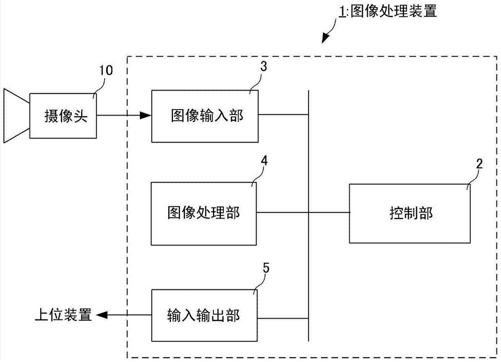
[0036] figure 1 It is a diagram showing a configuration of a main part of an image processing device according to an embodiment of the present invention.

[0037] This image processing device 1 includes a control unit 2 , an image input unit 3 , an image processing unit 4 , and an input / output unit 5 .

[0038] The control unit 2 controls the operations of various parts of the main body of the image processing device 1 .

[0039] The image input unit 3 inputs a frame image of an imaging range captured by the camera 10 . The camera 10 may be integrally provided on the main body of the image processing device 1 , or may be a frame formed independently from the main body of the image processing device 1 . When the camera 10 is a housing formed separately from the main body of the image processing device 1 , the camera 10 is connected to the main body of the image pr...


PUM


Abstract

An image processing device capable of effectively reducing power consumption and prolonging the service life is provided. A frame image of an imaging area imaged by a camera is input by an image input unit. An image processing unit is configured to process the frame image input to the image input unit and detect an object imaged in the frame image. In addition, the image processing unit is configured to determine a frequency of an operation clock according to the number of objects detected by the image processing unit.

Description

technical field [0001] The present invention relates to a technique for detecting a captured object by processing frame images of a shooting range captured by a camera. Background technique [0002] Conventionally, an image processing device has been provided that processes frame images of an imaging range captured by a camera, detects captured objects such as people and cars, and tracks the detected objects (see Patent Document 1, etc.). A conventional general image processing device, as shown in Patent Document 1, etc., generates a difference image (background difference image) between a frame image of a shooting range captured by a camera and a background image of the shooting range, two time-continuous The differential image of each frame image (inter-frame differential image), etc., to detect and track objects. [0003] prior art literature [0004] patent documents [0005] Patent Document 1: Japanese Patent Application Laid-Open No. 9-265585 [0006] However, in c...

Claims


Application Information

Patent Timeline
Patent Type & Authority Applications(China)
IPC IPC(8): H04N7/18G08B13/196G06T7/00
CPCG06V20/52G06V10/96
Inventor 田中文三小暮正道东乡康二梶谷浩一郎
Owner OMRON CORP
Features
  • Generate Ideas
  • Intellectual Property
  • Life Sciences
  • Materials
  • Tech Scout
  • Unparalleled Data Quality
  • Higher Quality Content
  • 60% Fewer Hallucinations
Learn More