Parking lock

A technology of parking locks and locking teeth, applied in the direction of brakes, vehicle components, brake types, etc., can solve problems such as multiple structural spaces and achieve good integration effects

Inactive Publication Date: 2014-07-16
SCHAEFFLER TECH AG & CO KG
View PDF6 Cites 14 Cited by
  • Summary
  • Abstract
  • Description
  • Claims
  • Application Information

AI Technical Summary

Problems solved by technology

Moreover, a parking lock of this type re

Method used


Image

  • Parking lock
  • Parking lock
  • Parking lock

Examples


Embodiment Construction

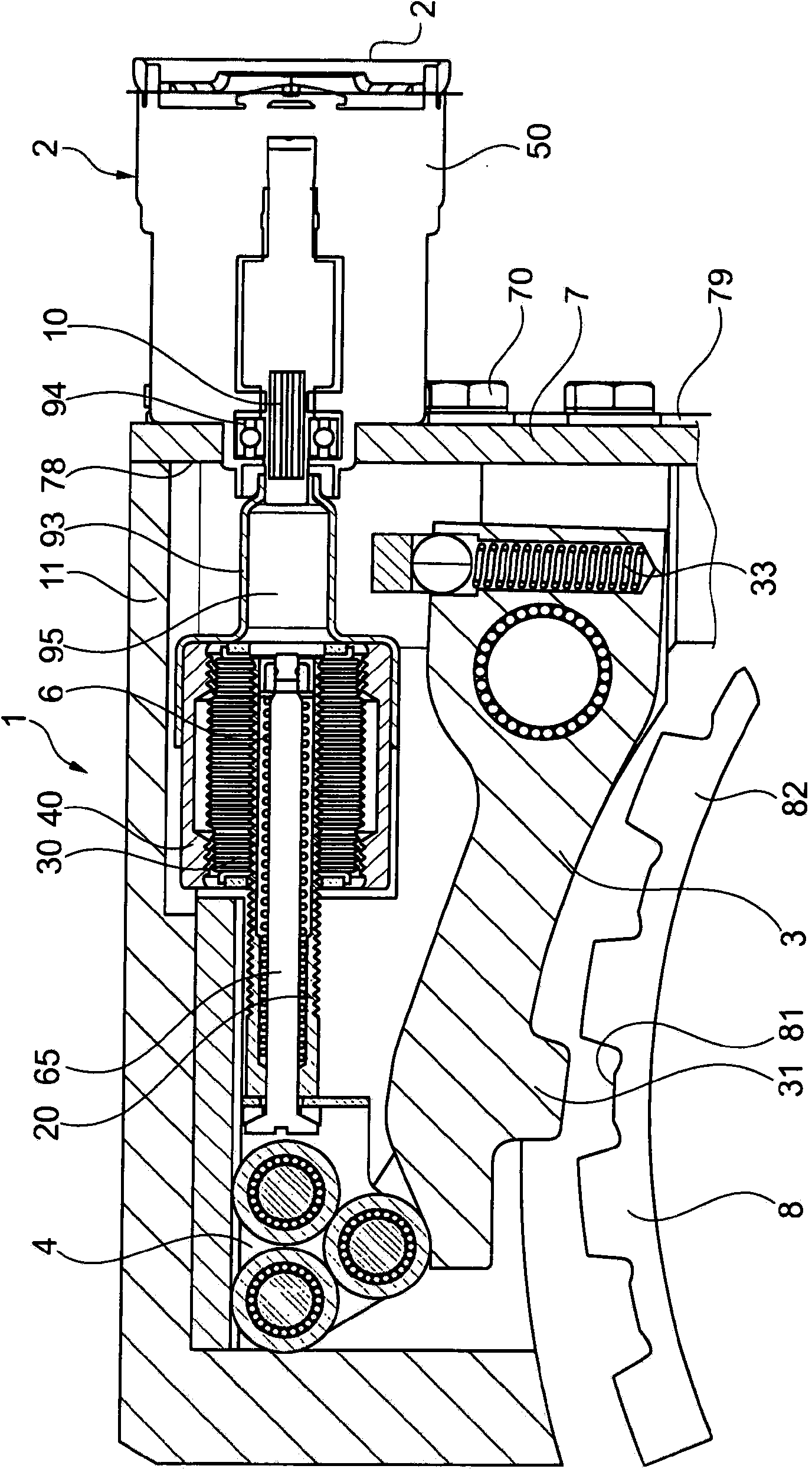
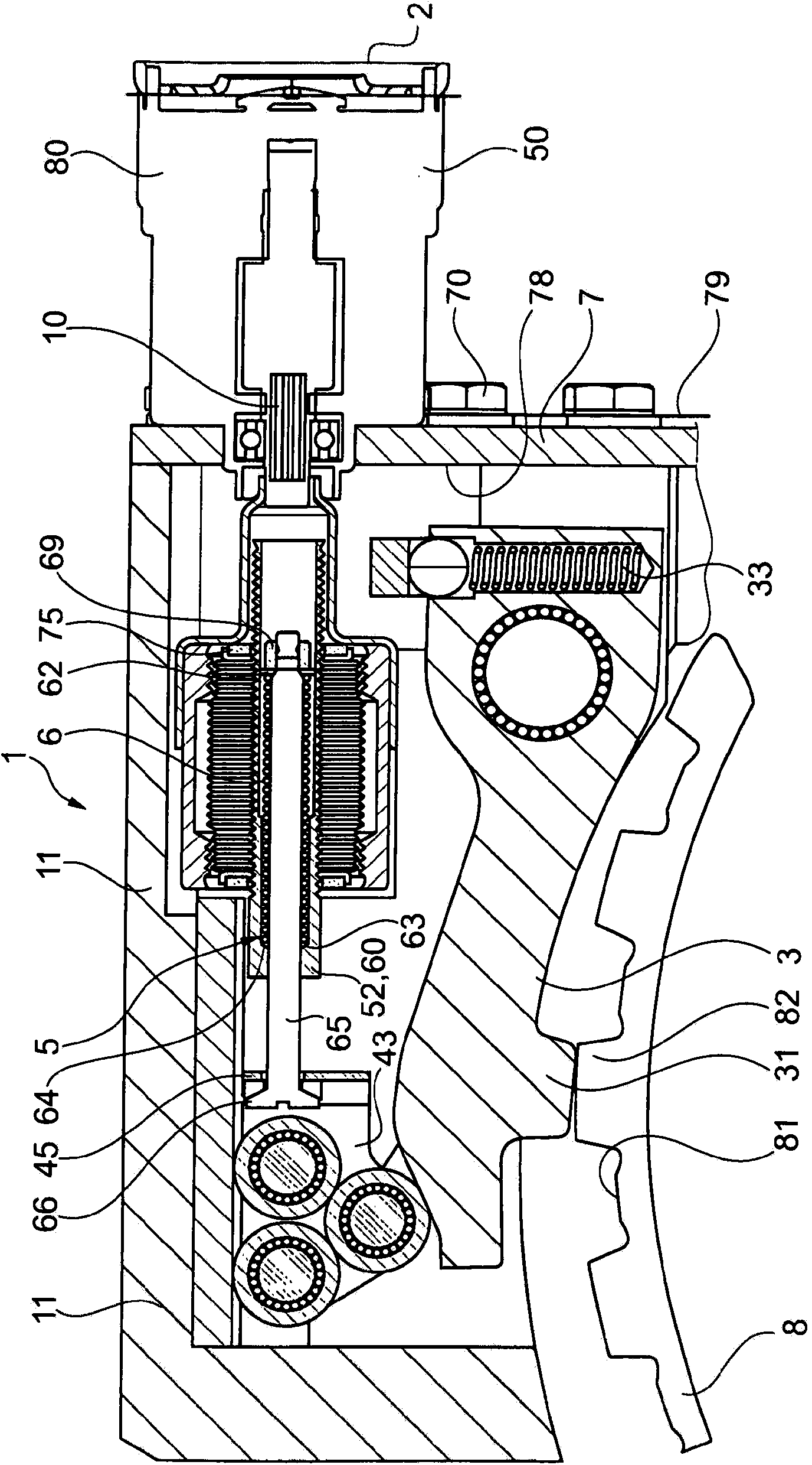
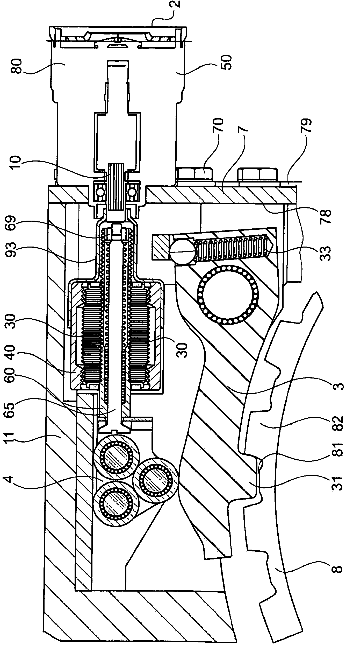
[0025] Depend on Figure 4 The basic operating principle of the parking lock 1 is shown. The actuator 2 acts on the operating unit 5 . The actuator 2 is shown schematically here and can be designed not only as a mechanical rod, cable, lever but also as an electric motor. The actuator 2 can also be formed as a pressure accumulator, especially if a hydraulic or compressed air medium is provided in the vicinity of the transmission. The actuator is arranged coaxially with respect to the offset force direction 51 of the actuating unit 5 . At this point, the coaxially arranged hollow shaft electric motor 22 engages mechanically via a planetary roller drive into the actuating lever 52 . The cylindrical actuating rod 52 is shown only schematically and has a thread 53 on its radial side 59 . The thread 53 meshes with the ring gear 40 via the planet gear 30 as the screw of the sun gear. ( Figures 1 to 3 ).

[0026] The operating lever 52 has a blind hole 61 in which the spring e...


PUM


Abstract

The invention relates to a parking lock (1) for a motor vehicle, having a lock catch (3) that can be pivoted about a rotational axis (d) and having a catch tooth (31) for engaging with a locking toothed portion (82), an actuation unit (5) which can be mechanically coupled to the lock catch (3) and by means of which the catch tooth (31) can be brought reversibly into engagement against the locking toothed portion (82), wherein the actuation unit (5) can be actuated by means of an actuator (2), wherein the actuator (2) acts on the actuation unit (5) by means of a planetary rolling gear, the planetary rolling gear has a sun wheel (2), a planet (30) and a hollow wheel (40), and the actuator (2) has a rotor shaft (10) which is fixedly connected to a wheel (20, 30, 40) of the planetary rolling gear.

Description

technical field [0001] The invention relates to a parking lock for a motor vehicle, in particular for an automatic transmission or a vehicle with an electric drive. Background technique [0002] Parking locks are used in the transmission of motor vehicles to ensure that the vehicle does not slip unintentionally. Especially when non-mechanical components are used in the drive train of a motor vehicle, as in the case of an automatic transmission with a torque converter, parking lock with the vehicle parked or with the engine switched off The device guarantees the position of the vehicle. For this purpose, the parking lock can be activated by the driver or indirectly by an electric auxiliary. It then normally engages the transmission output shaft in a form-locking manner. [0003] In DE 1043829A1 of the same type, the parking lock is provided in the form of a locking pawl which can pivot against a return force, and which can be positively engaged by means of pawl teeth in an...

Claims


Application Information

Patent Timeline
IPC IPC(8): B60T1/00F16D63/00
CPCB60T1/005F16D63/006F16D2121/005F16D2125/28F16D2125/36F16D2125/40F16H63/34F16H63/3425F16H63/3466
Inventor 托马斯·斯米塔那维克托·利希滕瓦尔德
Owner SCHAEFFLER TECH AG & CO KG
Why Eureka
Try Eureka