High speed horizontal electroforming apparatus for manufacturing metal foil and method for manufacturing metal foil

A manufacturing method, metal foil technology, applied in electroforming, electrolytic process, electrolytic components, etc., can solve the problems of reduced electrolyte flow velocity, difficult drum surface management, drum tank replacement restrictions, etc., to achieve stable electrolysis Analysis, excellent surface roughness, eddy current prevention effect

Inactive Publication Date: 2014-07-16
POHANG IRON & STEEL CO LTD
View PDF11 Cites 2 Cited by
  • Summary
  • Abstract
  • Description
  • Claims
  • Application Information

AI Technical Summary

Problems solved by technology

In the case of using such a drum tank to produce metal foil by electroforming, in order to manufacture a metal foil with a uniform thickness and surface roughness, it is very important to manage the surface of the drum tank. For this, The need to interrupt the operation of the entire process, making continuous management of the drum groove surface difficult
[0006] In addition, the speed of producing metal foil using the electroforming method is affected by the surface area of ​​the drum tank immersed in the electrolyte, so there are disadvantages that the size of the drum tank used for electroforming limits the production speed, and the huge drum tank Can consume a lot of cost, and the replacement of the drum tank is very limited
In addition, in order to increase the production speed, it is necessary to increase the flow speed of the electrolyte between the anode and the cathode, but the shape between the anode and the cathode is formed in a curvature, so there is a limit point where the flow speed of the electrolyte gradually decreases

Method used


Image

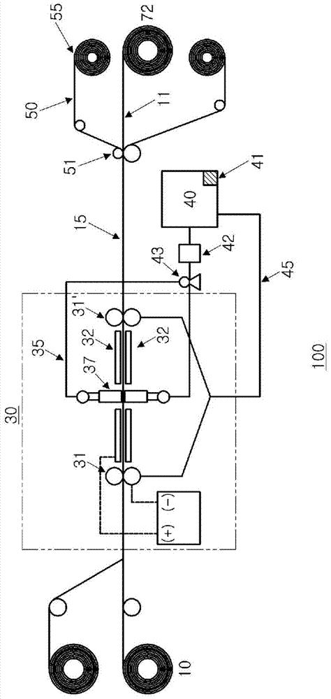
  • High speed horizontal electroforming apparatus for manufacturing metal foil and method for manufacturing metal foil
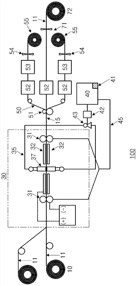
  • High speed horizontal electroforming apparatus for manufacturing metal foil and method for manufacturing metal foil
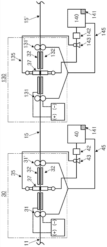
  • High speed horizontal electroforming apparatus for manufacturing metal foil and method for manufacturing metal foil

Examples


Embodiment 1

[0136] In addition to using an anode electrode (horizontal anode electrode) having a uniform thickness with respect to the width direction as a whole, and an embodiment of the present invention such as image 3 Except for the curved anode electrode shown (not divided into sub-electrodes), simulation experiments were carried out on the premise that the same equipment was used and an electrolyte solution was supplied between the mother plate and the anode electrode.

[0137] At this time, the overall width of the motherboard was 1000 mm, and the electrolytic solution was supplied by setting the Reynolds number of Re=1000 as a laminar flow condition.

[0138] From the experimental results, the current density distribution in the width direction of the motherboard was measured and in Figure 9 show. exist Figure 9In , the position refers to the position in the width direction of the mother board with the electrolyte supply pipe as a reference, and the results for half the width...

Embodiment 2

[0143] As the electrolyte supply tube, a tube with such as Figure 10 The electrolyte supply nozzle of the structure of (a) and has such as Figure 10 (b) and Figure 10 In order to analyze the degree of stabilization of the electrolyte flow field at the time of supplying the curved injection nozzles of the structure in (c), simulation experiments were performed on the case of supplying laminar flow and turbulent flow electrolyte to each nozzle.

[0144] The streamlines of the electrolyte flow field based on the simulation experiment were respectively in Figure 11 and Figure 12 show. Figure 11 Shows the streamlines when the electrolyte is supplied in a laminar flow with a Reynolds number of Re=1000, Figure 12 The streamlines when the electrolytic solution is supplied in a turbulent flow with a Reynolds number of Re=5000 are shown.

[0145] It can be known that in the case of supplying the electrolyte in a laminar flow field, if Figure 11 (a), when used with Figure...


PUM

PropertyMeasurementUnit
thicknessaaaaaaaaaa

Abstract

The present invention relates to an apparatus and a method for manufacturing metal foil by electroforming. Provided is a horizontal electroforming apparatus comprising: base plate supply means for continuously supplying flexible and conductive base plates to be provided as cathode electrodes in one horizontal direction; a horizontal cell including a conductor roll which contacts a widthwise edge portion of the base plate to transfer the base plate and supply current to the base plate, anode electrodes arranged at one side of the base plate or spaced apart from each other at both respective sides of the base plate, an electrolyte supply device for supplying an electrolyte containing metal ion through a horizontal path formed by the base plates and the anode electrodes, and current supply devices arranged at one side or both sides of the base plate to supply current to the conductor roll and to the anode electrodes so as to enable electroseparation of the metal ion; and delaminating means for delaminating, from the base plate, metal foil electrodeposited at one side or both sides of the base plate.

Description

technical field [0001] The present invention relates to a manufacturing method and equipment for high-speed manufacturing of metal foil, in particular to a manufacturing method for continuously manufacturing metal foil by electroforming and a manufacturing equipment for manufacturing the metal foil. Background technique [0002] In general, the rolling method and the electroforming method are widely used as the manufacturing method of metal foil: In the rolling method, a slab manufactured by ironmaking, steelmaking, and continuous casting is rolled to manufacture foil ; Or, in the electroforming method, the copper foil is produced by using a drum cell. [0003] Utilize the production of thin plate (foil) by the rolling method, which is the most common method, reheat the slab and perform hot rolling to manufacture metal foil with a thickness of about several mm. The produced sheet is additionally cold-rolled to produce extremely thin foils with a thickness of less than 100 μ...

Claims


Application Information

Patent Timeline
Patent Type & Authority Applications(China)
IPC IPC(8): C25D1/04C25D1/20C25D17/00C25D21/12
CPCC25D1/20C25D1/00C25D1/04
Inventor 金弘浚金珍有李载坤崔在勋金星茁崔锡欢赵云宽
Owner POHANG IRON & STEEL CO LTD
Why Eureka
Try Eureka