
Hydraulic examination bed

A diagnostic bed and hydraulic technology, applied in the field of medical equipment, can solve problems such as the abnormal use of the diagnostic bed, high cost of electric diagnostic bed equipment, complex structure, etc., and achieve the effect of convenient implementation, simple structure and low cost

Active Publication Date: 2014-07-23
JIANGSU SAIKANG MEDICAL EQUIP
View PDF8 Cites 13 Cited by
  • Summary
  • Abstract
  • Description
  • Claims
  • Application Information

AI Technical Summary

Problems solved by technology

However, the bed board of the traditional examination bed is a whole, that is to say, the patient can only lie flat. When the examination needs to be half-sitting and half-lying, the examination bed cannot realize the physical examination of the patient. At the same time, it corresponds to different doctors. , it requires different heights of the bed, and the height of the traditional examination bed is not constant, therefore, this kind of examination bed brings great inconvenience to the examination work of the examination doctor
[0003] In view of the above defects, Chinese invention patent CN 103222919A discloses an electric examination bed, although it solves the above technical problems, but in special occasions, there is no power supply At the same time, the examination bed cannot be used normally. At the same time, the cost of equipment used in the electric examination bed is relatively high, and the structure is relatively complicated.

Method used


Image

  • Hydraulic examination bed
  • Hydraulic examination bed
  • Hydraulic examination bed

Examples


Embodiment Construction

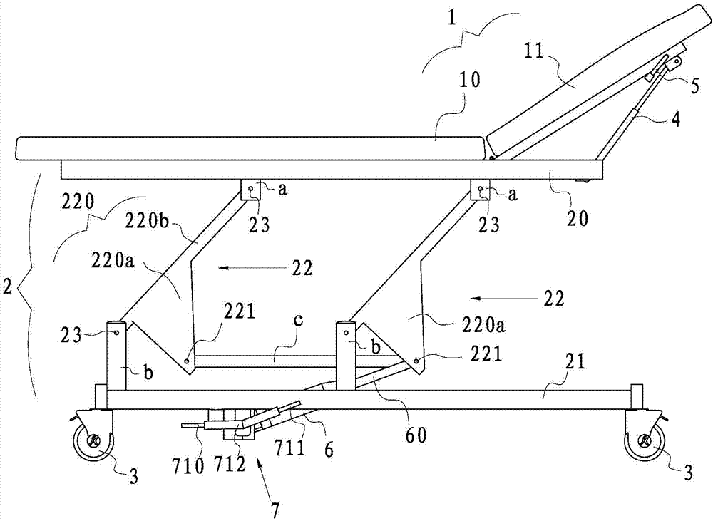
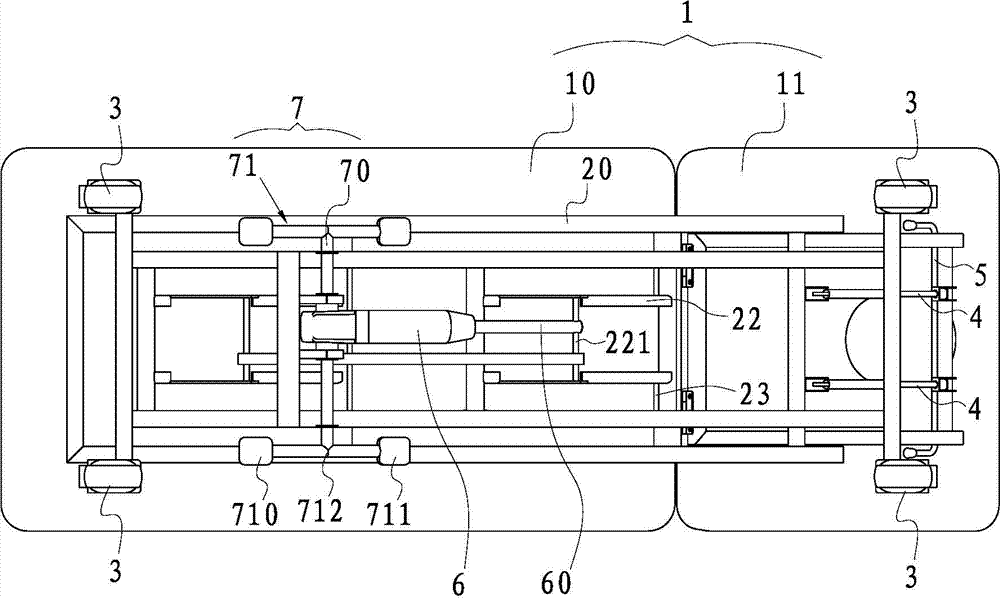
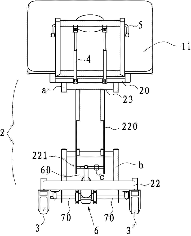
[0021] Such as Figure 1 to Figure 3 As shown, the hydraulic examination bed of this embodiment includes a bed 1 , a bed frame 2 , and wheels 3 at the bottom of the bed frame 2 .

[0022] Wherein, the bed frame 2 includes an upper frame 20 extending horizontally at the bottom of the lying part 10, a lower frame 21 positioned below the upper frame 20, and a bracket 22 for connecting the upper frame 20 and the lower frame 21. The bed body 1 includes The lying part 10 arranged horizontally and the backrest part 11 rotatably connected with the upper bracket 20, when lying flat, the lying part 10 is set flush with the backrest part 11, and the backrest 11 is adjusted when half-sitting and half-lying are required. Adjust the angle of the back 11 and the lying part 10 to meet the inspection requirements or the patient's comfortable angle; the wheels 3 are located at the bottom of the lower bracket 21, and the wheels 3 in this example are silent universal wheels. For different pl...


PUM


Abstract

The invention relates to a hydraulic examination bed. The hydraulic examination bed comprises a bed body, a bed frame and wheels. The bed body comprises a lying portion and a back leaning portion, the bed frame comprises an upper support, a lower support and supporting frames, the supporting frames comprise supporting frame bodies located on the two sides of the upper support and the lower support and arranged in an inclined mode from top to bottom and connecting frames used for connecting the supporting frame bodies located on the two sides, and the two ends of each supporting frame body are connected to the upper support and the lower support through rotation shafts in a rotating mode respectively. The hydraulic examination bed further comprises a plurality of gas springs, a gas spring control valve, a hydraulic cylinder located at the bottom of the lying portion and used for driving the supporting frames to rotate around the rotation shafts so as to enable the upper support to rise or fall and a power mechanism which can be used for adjusting stretching and contracting of a telescopic rod of the hydraulic cylinder through hands or feet. The end of the telescopic rod is connected to the connecting frames. On various occasions, rising and falling of the examination bed can be realized, angle adjustment of the back leaning portion can further be realized, the structure is simple and the manufacturing cost is low.

Description

technical field [0001] The invention belongs to the technical field of medical equipment, in particular to a hydraulic diagnosis bed. Background technique [0002] In hospitals, examination beds are very common. They are mainly special beds for medical staff to check the body of patients, and can also be used for infusion of patients. However, the bed board of the traditional examination bed is a whole, that is to say, the patient can only lie flat. When the examination requires half-sitting and half-lying, the examination bed cannot realize the physical examination of the patient. At the same time, it corresponds to different doctors. , it needs different height positions of the bed, and the height of the traditional examination bed is not constant, therefore, this kind of examination bed brings great inconvenience to the examination work of the examination doctor. [0003] In view of the above defects, Chinese invention patent CN 103222919A discloses an electric examinati...

Claims


Application Information

Patent Timeline
IPC IPC(8): A61G13/06A61G13/08A61B19/00
Inventor 蔡悦恺
Owner JIANGSU SAIKANG MEDICAL EQUIP
Learn More