
Infrared image recognition method and system based on visual processing and multi-feature fusion

A multi-feature fusion and infrared image technology, which is applied in character and pattern recognition, image analysis, image enhancement, etc., can solve the problems of low signal-to-noise ratio and contrast, imperfection, and object shape deformation of infrared images, so as to improve real-time performance and reliability, shorten the detection time, and solve the effect of misrecognition problems

Pending Publication Date: 2022-06-07
STATE GRID SHANDONG ELECTRIC POWER +1
View PDF0 Cites 1 Cited by
  • Summary
  • Abstract
  • Description
  • Claims
  • Application Information

AI Technical Summary

Problems solved by technology

[0004] 1) Infrared thermal imaging technology reflects the temperature field information, which will cause serious deformation of the object shape
This technology cannot effectively locate and identify the infrared images of substation equipment, resulting in the inability to accurately map the corresponding relationship between temperature field information and electrical equipment and its various parts in the image;
[0005] 2) In order to identify substation equipment through infrared image intelligent recognition technology, we have accumulated a large amount of infrared image data resources, but traditional machine learning algorithms cannot effectively use these data resources, and cannot effectively troubleshoot substation equipment diagnosis;
The overall distribution of infrared image grayscale is low and concentrated, and due to the random interference brought by the surrounding environment to the infrared imaging process and the imperfection of the thermal imaging system itself, the signal-to-noise ratio and contrast of infrared images are relatively low
Therefore, the recognition of power equipment through infrared images has high requirements for target detection and positioning algorithms. Traditional visual recognition algorithms cannot meet the needs of equipment recognition in such complex scenarios.

Method used


Image

  • Infrared image recognition method and system based on visual processing and multi-feature fusion
  • Infrared image recognition method and system based on visual processing and multi-feature fusion
  • Infrared image recognition method and system based on visual processing and multi-feature fusion

Examples


Embodiment Construction

[0048] The present invention will be further described below with reference to the accompanying drawings and embodiments.

[0049] It should be noted that the following detailed description is exemplary and intended to provide further explanation of the invention. Unless otherwise defined, all technical and scientific terms used herein have the same meaning as commonly understood by one of ordinary skill in the art to which this invention belongs.

[0050] It should be noted that the terminology used herein is for the purpose of describing specific embodiments only, and is not intended to limit the exemplary embodiments according to the present invention. As used herein, unless the context clearly dictates otherwise, the singular is intended to include the plural as well, furthermore, it is to be understood that when the terms "comprising" and / or "including" are used in this specification, it indicates that There are features, steps, operations, devices, components and / or com...


PUM


Abstract

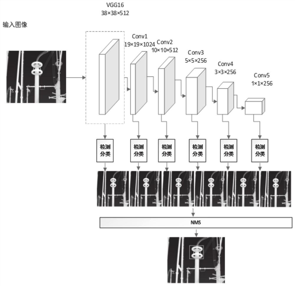
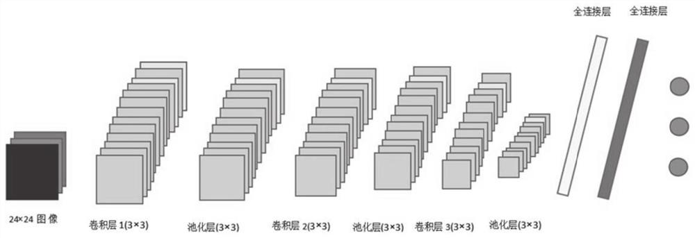
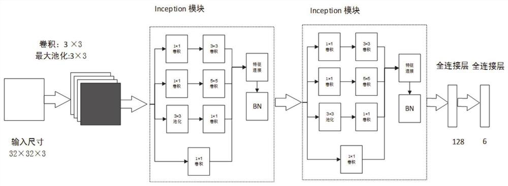
The invention provides an infrared image recognition method and system based on visual processing and multi-feature fusion, and the method comprises the steps: processing a collected infrared image through employing an image preprocessing technology, so as to filter the interference of a background and other factors on equipment recognition, carrying out the target detection of the infrared image through employing a target detection model based on VGG-Net multi-feature fusion, and carrying out the recognition of a target image. And the position of the power equipment in the infrared image is positioned, and the type of the positioned power equipment is identified by using the trained equipment classification model, so that the accuracy of infrared image equipment positioning and identification can be ensured, and the requirements of substation scene robot inspection can be met.

Description

technical field [0001] The invention belongs to the technical field of inspection robots and computer vision, and relates to an infrared image recognition method and system based on visual processing and multi-feature fusion. Background technique [0002] The statements in this section merely provide background information related to the present invention and do not necessarily constitute prior art. [0003] The research on the detection and fault diagnosis of electrical equipment using infrared thermal imaging technology has been vigorously carried out at home and abroad, and this technology has also been widely used in the existing substation inspection robot system. Infrared thermal imaging technology is a non-contact, passive measurement technology. It can detect and diagnose a large number of internal and external defects of power equipment, especially many faults that are inconvenient or impossible to detect by conventional test methods. However, according to the inv...

Claims


Application Information

Patent Timeline
Patent Type & Authority Applications(China)
IPC IPC(8): G06T7/00G06K9/62G06T5/00G06T5/40G06N3/04G06N3/08G06V10/80G06V10/82
CPCG06T7/0002G06T5/40G06N3/08G06T2207/10048G06T2207/20024G06N3/045G06F18/253G06T5/70
Inventor 胥明凯何峰胡旭冉刘斌慕世友任志刚周大洲黄锐郭锐王海鹏张德才鲍新
Owner STATE GRID SHANDONG ELECTRIC POWER
Learn More