Optimisation of a device for painting work pieces

A workpiece and coating technology, applied in the direction of cleaning device, spraying device, liquid spraying device, etc., can solve the problem of inability to coat paint

Inactive Publication Date: 2014-07-23
VENJAKOB MASCHBAUU
View PDF5 Cites 8 Cited by
  • Summary
  • Abstract
  • Description
  • Claims
  • Application Information

AI Technical Summary

Problems solved by technology

[0003] A deficiency of the state of the art is that it is not possible to apply the coating to the workpiece with little loss to the extent that the recovery efficiency of the coating is optimizable

Method used


Image

  • Optimisation of a device for painting work pieces
  • Optimisation of a device for painting work pieces
  • Optimisation of a device for painting work pieces

Examples


Embodiment Construction

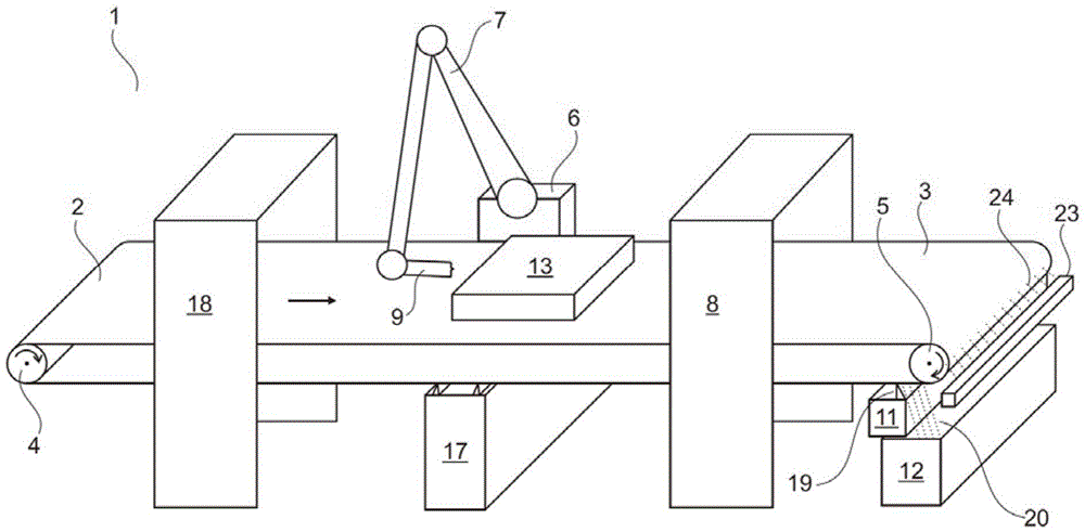
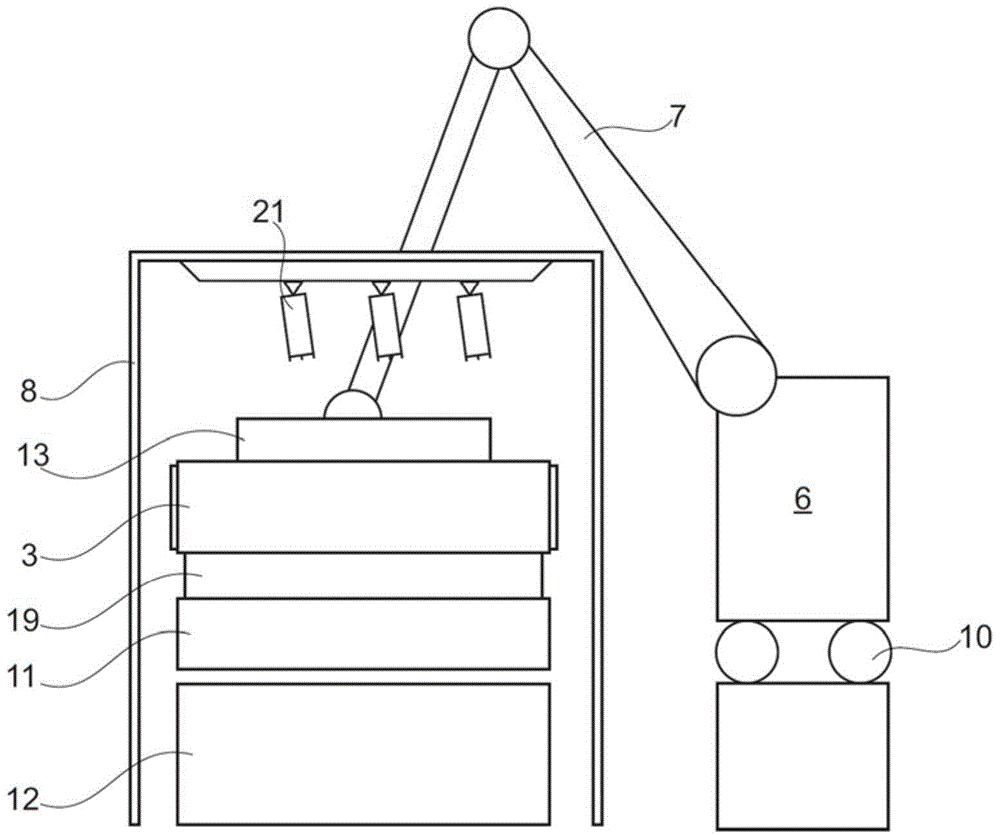
[0073] figure 1 is a side view of an apparatus for coating workpieces according to the invention. The device 1 for coating workpieces has a simple structure and basically consists of the following parts: a belt conveyor 2 , a paint spraying robot 6 and a surface spraying machine 8 , and a three-dimensional part detection device (3D part detection device) 18 .

[0074] The belt conveyor 2 has a conveyor belt 3 , a first tail pulley 4 and a second tail pulley 5 . The conveyor belt 3 is driven by one of the first tail pulley 4 and the second tail pulley 5 . The conveyor belt 3 transports the workpieces to be coated from the three-dimensional part inspection device 18 to the paint spraying robot 6 and then to the surface spraying machine 8 (see arrow on the conveyor belt 3 ). During the following coating process, the fully coated workpieces are conveyed by the conveyor belt 3 .

[0075] The paint removal apparatus 11 (paint removal apparatus) has a scraping device 19 (scraping ...


PUM


Abstract

The device (1) has a rotating drivable belt conveyer (2) for transporting the workpieces (13) to be painted. The color spraying robot (6) and the surface spraying machine (8) are configured to paint the side surfaces and top surfaces of the workpiece to be painted. The color spraying robot is configured to paint the contour surfaces lying inside the workpiece to be painted, and is provided with a spray gun (9) which is movable around several axles. The color spraying robot is movable along the supplementary auxiliary axis. An independent claim is included for method for painting workpieces.

Description

technical field [0001] The invention relates to a device for coating workpieces. Background technique [0002] The current state of the art contains a large number of different possibilities for coating workpieces, eg coating systems with floor and overhead conveyor systems, spindle chain conveyors Or robot coating systems for surface spray coating systems. [0003] A drawback of the current state of the art is that it is not possible to achieve an almost loss-free application of paint onto the workpiece to such an extent that the recovery efficiency of the paint is optimizable. [0004] It is therefore an object of the present invention to provide a paint spray system which overcomes the deficiencies of the state of the art. Contents of the invention [0005] It is therefore an object of the present invention to provide a paint spraying system which applies paint to said workpieces with little loss and which enables a reasonable level of paint recovery. [0006] The in...

Claims


Application Information

Patent Timeline
Patent Type & Authority Applications(China)
IPC IPC(8): B05B13/02B05B13/04B05B15/04B05B14/00B05B14/20B05B15/68
CPCB05B14/00B05B12/122B05B13/0447B05B13/0457B65G45/24B05B13/0473B25J9/0093B25J11/0075B05B16/95B05B14/20Y02P70/10B05B13/0431B05B13/0478B05B9/03
Inventor C·室特赖特J·福格特
Owner VENJAKOB MASCHBAUU
Why Eureka
Try Eureka