Multifunctional full-automatic steel bar bending and forming machine

A fully automatic and multi-functional technology, applied in the field of multi-functional fully automatic steel bar bending and forming machines, can solve the problems of high labor intensity, low production efficiency, complex adjustment and maintenance, and achieve high labor efficiency, bending angle and The effect of convenient length adjustment

Active Publication Date: 2014-07-23
WEIFANG HUAYAO MAGNETOELECTRIC MACHINERY
View PDF7 Cites 18 Cited by
  • Summary
  • Abstract
  • Description
  • Claims
  • Application Information

AI Technical Summary

Problems solved by technology

The traditional method is to manually bend the steel bar, the labor intensity of the workers is high, and the production efficiency is low
A steel bar stirrup machine is disclosed in the patent application document No. 201020108516.5, which is provided with a fixed block and a rotating block, and the rotating block is driven to rotate by a force applying device, so that the steel bar placed between the rotating block and the fixed block For bending, the incoming steel bars need to be fed intermittently, and a separate straightening machine is required to straighten the steel bars, so the production efficiency is low; moreover, it uses racks and pinions for bending power drive, when the bending angle occurs When changing, adjustment and maintenance are complicated

Method used


Image

  • Multifunctional full-automatic steel bar bending and forming machine
  • Multifunctional full-automatic steel bar bending and forming machine
  • Multifunctional full-automatic steel bar bending and forming machine

Examples


Embodiment Construction

[0026] Below in conjunction with accompanying drawing, the specific embodiment of the present invention is described in further detail:

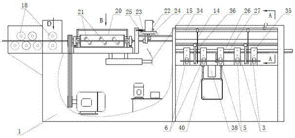
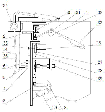
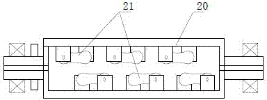
[0027] Such as figure 1 As shown, the multifunctional fully automatic steel bar bending forming machine provided by the present invention comprises a frame 1, and the rear portion of the frame 1 is sequentially equipped with a feeding device, a steel bar straightening device and a steel bar cutting device, and the frame 1 There are multiple bending devices that are arranged at intervals before and after and can slide along the frame. The horizontal height of the bending device is lower than the above-mentioned feeding device and steel bar cutting device. One of the bending devices is connected with a steel bar clamping device. , in this embodiment, the above-mentioned steel bar clamping device is provided on the third bending device counted from the back to the front, and the steel bar clamping device is detachable, so it can be installed on...


PUM


Abstract

The invention discloses a multifunctional full-automatic steel bar bending and forming machine which comprises a machine frame. A feeding device, a steel bar straightening device and a steel bar cutting-off device are installed on the machine frame, multiple bending devices are connected onto the machine frame, and a steel bar clamping device is connected onto one bending device. Each bending device comprises a bending frame connected onto the machine frame in a sliding mode, wherein a supporting shaft sleeve and a telescopic shaft are installed on the bending frame, the supporting shaft sleeve is further provided with a bending roller, a bending power device is installed on the bending frame, the supporting shaft sleeve is in power connection with a transmission chain wheel, a bending crank arm and a fixing column are further installed on the bending frame, a transmission chain is installed on the transmission chain wheel in a winding mode, two free ends of the transmission chain are respectively connected onto one supporting arm of the bending crank arm and the fixing column, a reset spring is installed between the transmission chain and the fixing column, the other supporting arm of the bending crank arm is in power connection with the bending power device, and the telescopic shaft is driven by a pulling power device. The multifunctional full-automatic steel bar bending and forming machine has the advantages of being high in labor efficiency and enabling a bending angle and the length to be adjustable quickly and conveniently.

Description

technical field [0001] The invention relates to a multifunctional fully automatic steel bar bending forming machine. Background technique [0002] In the construction industry, steel bars are widely used as the skeleton of concrete to increase the strength of concrete. The steel bars before use are placed in coils or bundles. When in use, the steel bars need to be straightened, cut and bent to form polygonal or bent stirrups. The traditional method is to manually bend the steel bars, which is labor-intensive and low in production efficiency. A steel bar stirrup machine is disclosed in the patent application document No. 201020108516.5, which is provided with a fixed block and a rotating block, and the rotating block is driven to rotate by a force applying device, so that the steel bar placed between the rotating block and the fixed block For bending, the incoming steel bars need to be fed intermittently, and a separate straightening machine is required to straighten the st...

Claims


Application Information

Patent Timeline
Patent Type & Authority Applications(China)
IPC IPC(8): B21F1/00B21F1/02B21F23/00
Inventor 牟刚张学昌温永成孙福全
Owner WEIFANG HUAYAO MAGNETOELECTRIC MACHINERY
Why Eureka
Try Eureka