Method and device for installation and correction of linear rolling guide rail of grinding machine

A technology of rolling guide and correction device, which is applied in the direction of grinding bed, grinding machine parts, grinding frame, etc., can solve the problems of damage position accuracy, low processing efficiency, long auxiliary time, etc., and achieve high correction accuracy. , Improve work efficiency, the effect of short auxiliary time

Active Publication Date: 2016-05-25
安徽省安达兴智能装备有限公司
View PDF1 Cites 0 Cited by
  • Summary
  • Abstract
  • Description
  • Claims
  • Application Information

AI Technical Summary

Problems solved by technology

The general method of installation and alignment is to install a dial indicator on the grinding wheel frame, and then calibrate point by point along the side of the rolling guide. Since the linear rolling guide is a slender workpiece, it is easily deformed during installation and must be calibrated side by side. Press it tightly, and when one point is corrected and then the next point is corrected, it will destroy the corrected position accuracy
Therefore, the auxiliary time spent on the installation and correction work before grinding the linear rolling guideway is long, and the processing efficiency is very low
Chinese document CN201110084439.3 discloses a method for installing and positioning linear guide rails, but this method requires injection of positioning glue, curing and molding, and many processes

Method used


Image

  • Method and device for installation and correction of linear rolling guide rail of grinding machine
  • Method and device for installation and correction of linear rolling guide rail of grinding machine
  • Method and device for installation and correction of linear rolling guide rail of grinding machine

Examples


Embodiment

[0022] Example: see Figure 1 to Figure 4 , a method for installing and correcting linear rolling guide rails of a grinding machine, comprising the following steps:

[0023] a. Place the linear rolling guide M on the magnetic work surface of the grinding machine;

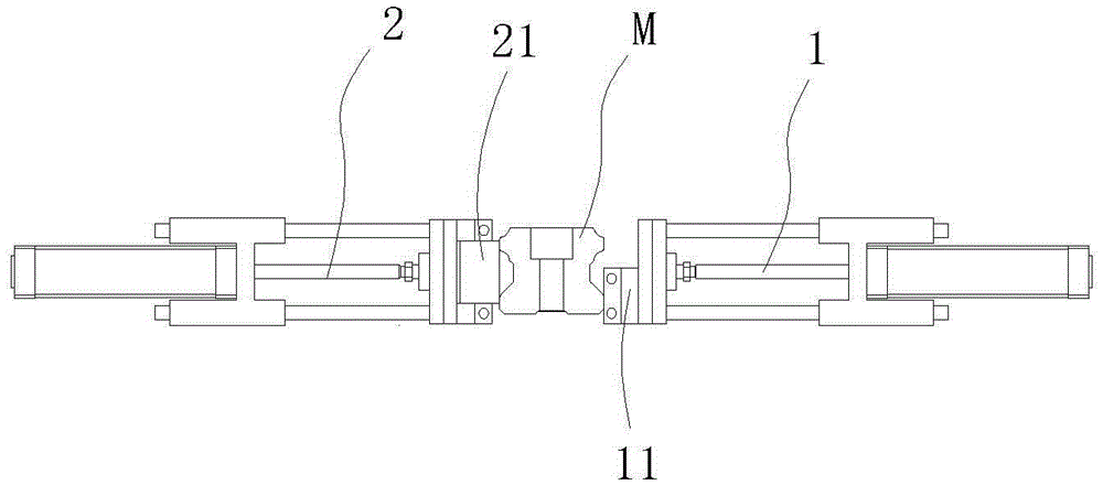
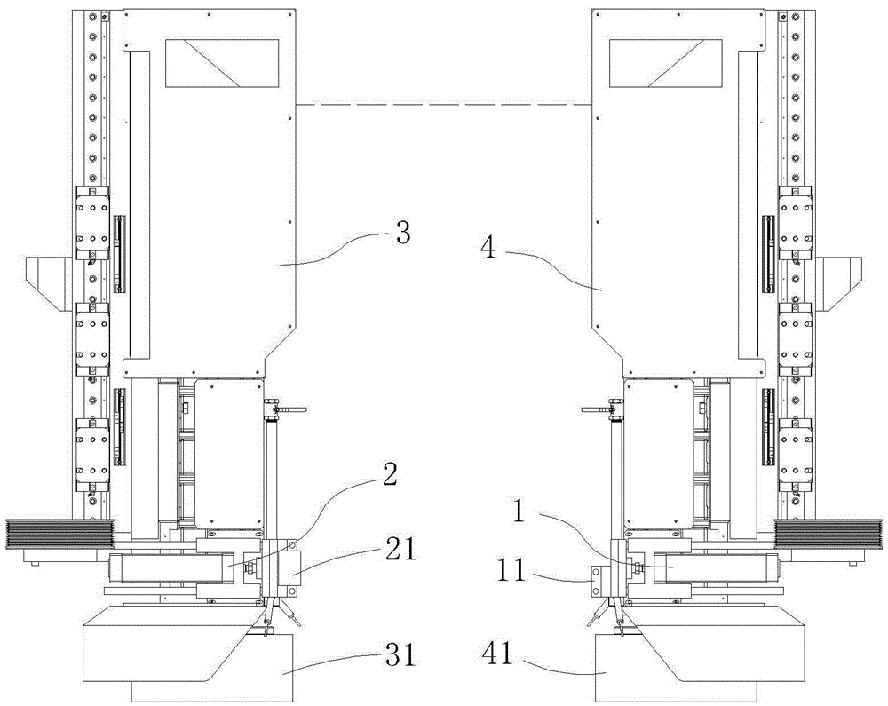
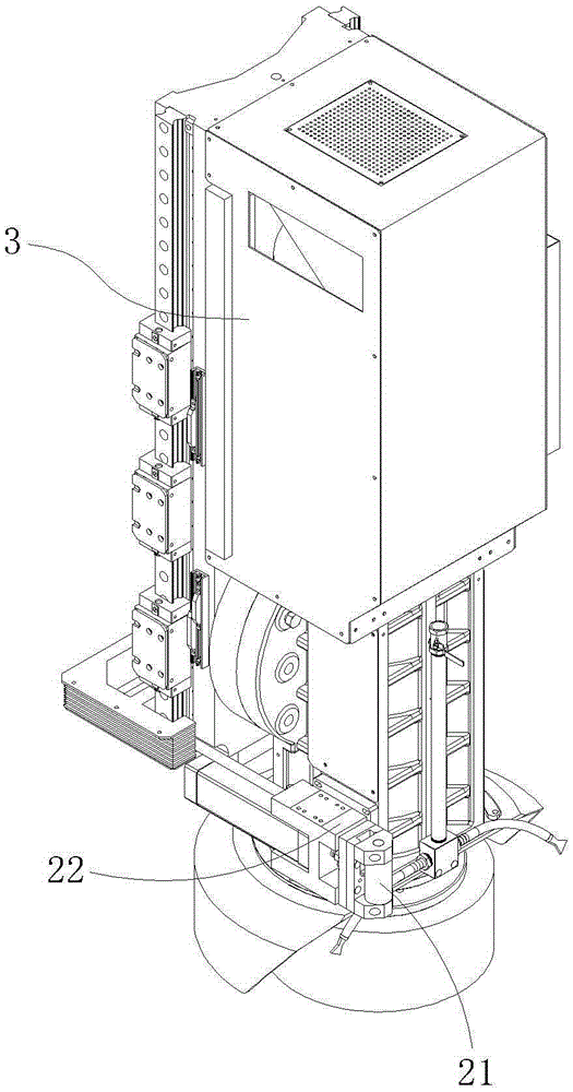
[0024] b. Move the correction device to the vicinity of the linear guide, first use the positioning block 11 connected to the reference cylinder 1 to press against the reference side of the linear guide for positioning, and then press the roller 21 of the cylinder 2 against the other side of the linear rolling guide Pressing up, the pressure set by the reference cylinder 1 is slightly larger than the pressure set by the pressing cylinder 2;

[0025] c. Start the grinder and move the correction device along the full length of the linear rolling guide with a slow moving speed. When the correction device moves, the reference position determined by the reference cylinder remains constant in the longitudinal direction o...


PUM


Abstract

The invention discloses a method and device for installing and correcting a grinder linear rolling guide rail. The device comprises a pressing cylinder and a standard cylinder. The pressing cylinder and the standard cylinder are arranged on a left grinding wheel spindle and a right grinding wheel spindle of a grinder respectively. A locating block of the standard cylinder abuts against the standard side face of the guide rail, a roller of the pressing cylinder on the other side tightly presses the other side face of the guide rail, a workpiece correcting device is moved, if certain deviation of the installing direction of the linear guide rail exists, the guide rail can be slightly moved to correct installation errors in the moving process, after the first time of moving and attraction force of a magnetic work table is increased, the second time of moving is executed to further correct the position of a workpiece, and therefore the standard side face of the linear guide rail is parallel to the longitudinal moving direction of the work table. The correcting device is used for correcting the standard side face of the linear guide rail to be parallel to the longitudinal moving direction of the work table, and the device has the advantages of being simple in operation, short in auxiliary time, high in correction precision, and the like.

Description

technical field [0001] The invention discloses a method and a device for installation and correction of linear rolling guide rails of a grinding machine, which belong to the technical field of installation and correction of workpieces processed by machine tools according to the International Patent Classification (IPC). Background technique [0002] Before processing the linear rolling guide, it is necessary to first find out the parallelism between the reference side and the longitudinal movement direction of the table. The general installation and alignment method is to install a dial indicator on the grinding wheel frame, and then correct it point by point along the side of the rolling guide. Since the linear rolling guide is a slender workpiece, it is easily deformed during the installation process and must be corrected while When the side is pressed tightly, when one point is corrected and then the next point is corrected, the corrected position accuracy will be destroy...

Claims


Application Information

Patent Timeline
Patent Type & Authority Patents(China)
IPC IPC(8): B24B41/02
CPCB24B49/00
Inventor 吴锦松陈永光吴人勇
Owner 安徽省安达兴智能装备有限公司
Why Eureka
Try Eureka