
Electromagnetic brake with air pressure damping structure

A technology of electromagnetic brake and damping structure, which is applied in the direction of hoisting device, etc., can solve the problems of complex structure, unsolved noise impact, etc., and achieve the effect of reducing noise

Inactive Publication Date: 2014-07-23
CHINA THREE GORGES UNIV
View PDF7 Cites 0 Cited by
  • Summary
  • Abstract
  • Description
  • Claims
  • Application Information

AI Technical Summary

Problems solved by technology

Its structure is relatively complex, and the defect of large noise impact has not been solved

Method used


Image

  • Electromagnetic brake with air pressure damping structure
  • Electromagnetic brake with air pressure damping structure
  • Electromagnetic brake with air pressure damping structure

Examples


Embodiment Construction

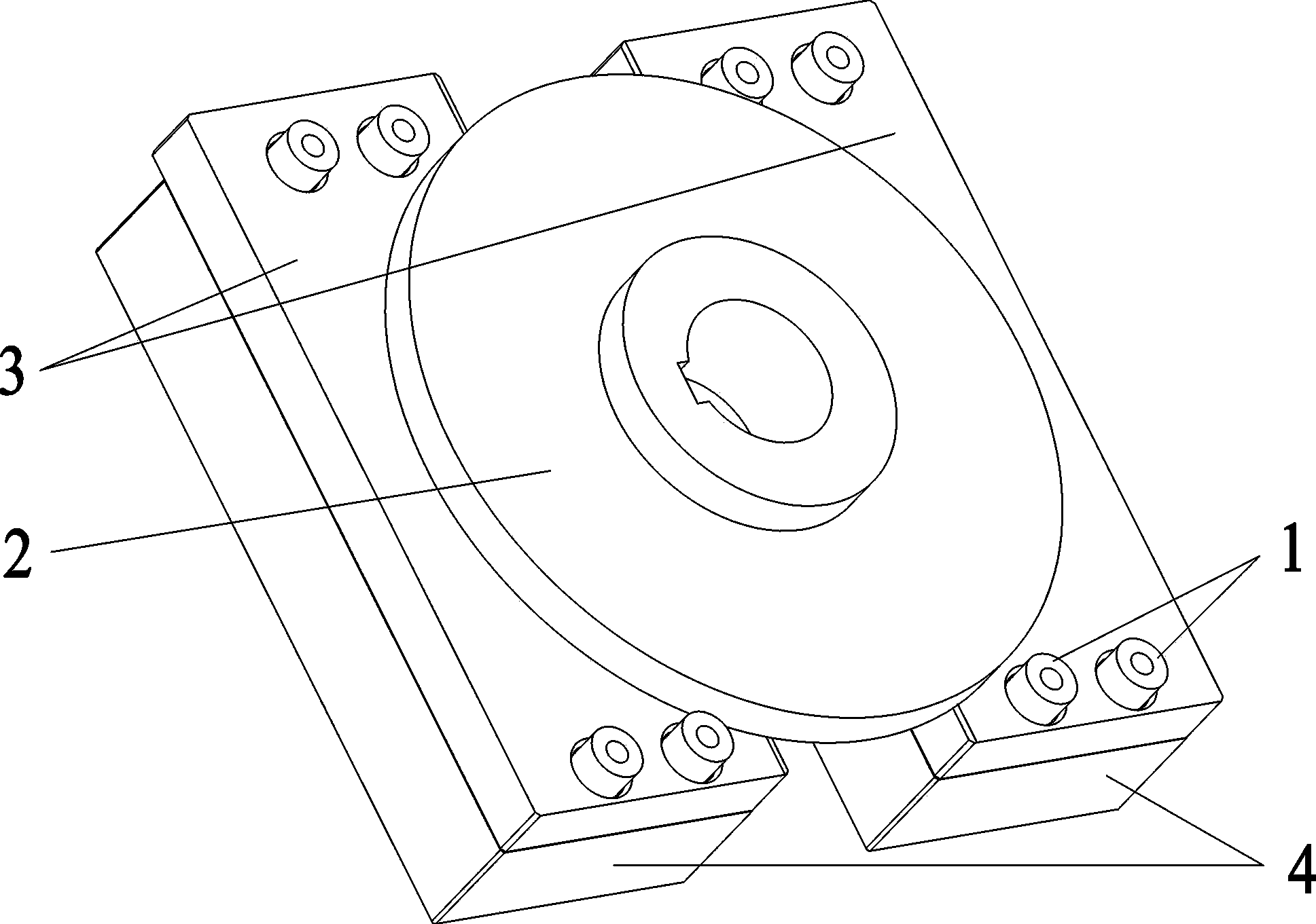
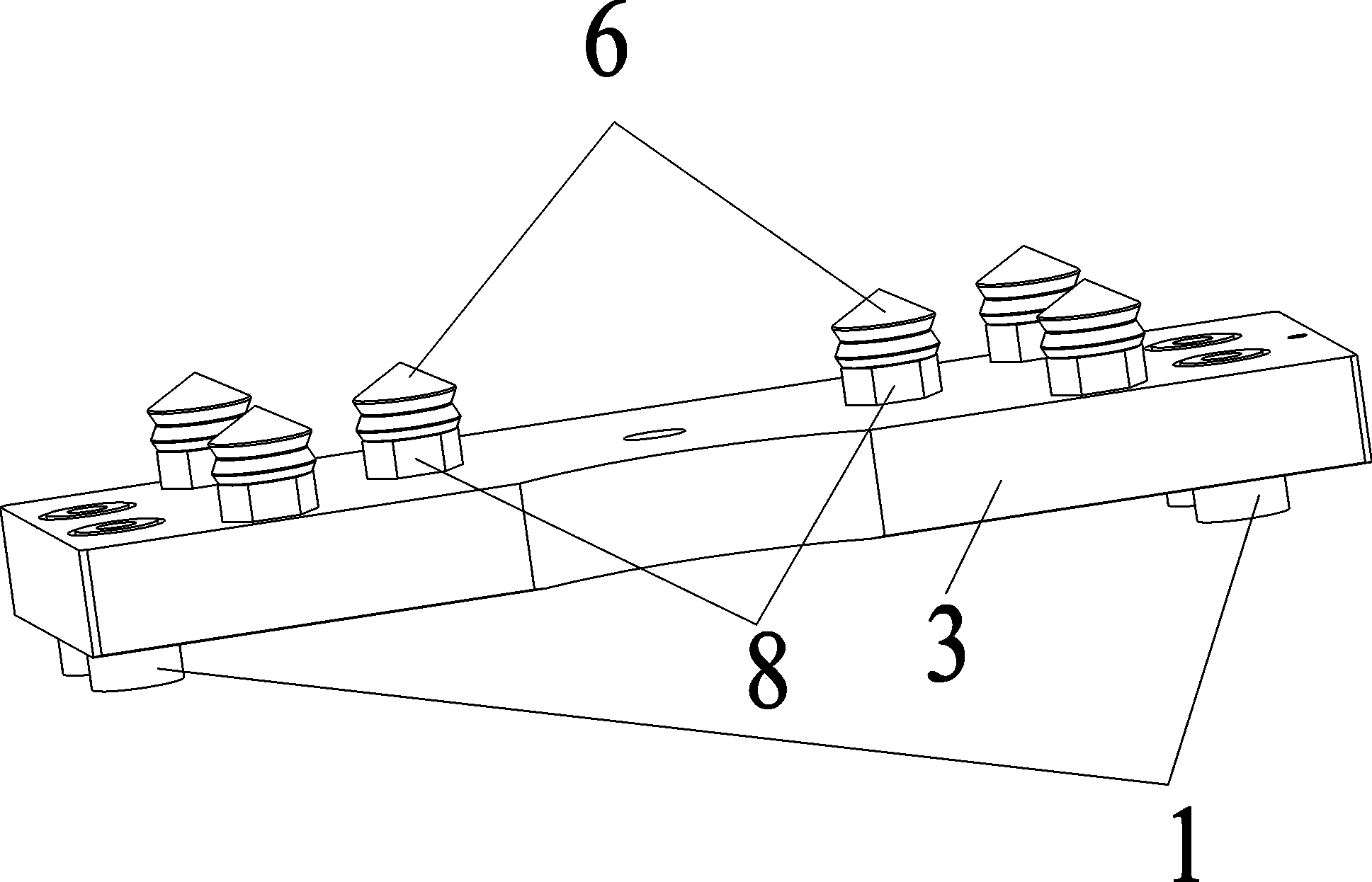
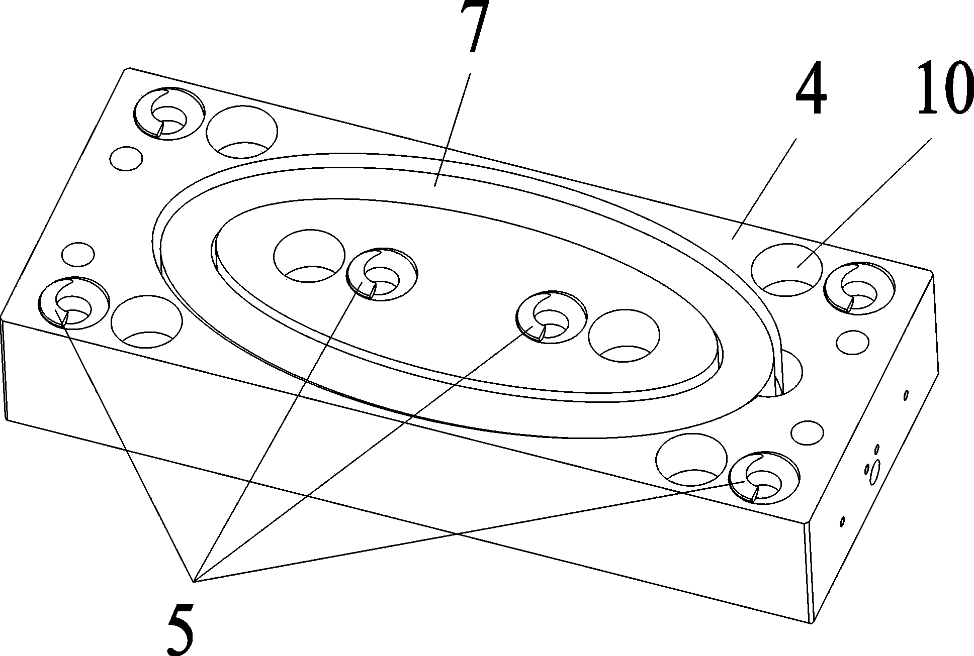
[0025] Such as Figure 1~6 Among them, an electromagnetic brake with a pneumatic damping structure, including an iron core 4 and an armature 3, is also provided with a friction plate 2 that forms a frictional fit with the armature 3, and a spring 5 that makes the armature 3 spring up is provided in the iron core 4, There is also a coil 7 that makes the armature 3 adsorb to the iron core 4. A plurality of plug cores 8 are arranged on the armature 3. The ends of the plug cores 8 are covered with rubber plugs 6. On the iron core 4, a plurality of plug cores 8 are provided. Blind hole 10 for mating plug core 8 .

[0026] Such as figure 1 Among them, the brake in this example is a normally closed brake, and the friction plate 2 is fixedly connected to the motor shaft. When the coil 7 is not energized, the spring 5 presses the armature 3 and the friction plate 2 tightly, and the motor cannot rotate. There is a gap of 0.4-0.8 mm between the armature 3 and the iron core 4, preferabl...


PUM


Abstract

An electromagnetic brake with an air pressure damping structure comprises an iron core and an armature, and further comprises a friction plate which is in friction fit with the armature. A spring which ejects up the armature and a coil which enables the armature to be attracted to the iron core are arranged in the iron core. A plurality of plug cores are arranged on the armature. A rubber plug is wrapped on the end of each plug core. A plurality of blind holes matched with the plug cores are formed in the iron core. When the coil is not powered on, the spring tightly presses the armature and the friction plate together, a motor can not rotate, and a gap 0.45 mm wide exists between the armature and the iron core. When the coil is powered on, the armature is folded together with the iron core and gets away from the friction plate, and the motor can rotate. The electromagnetic brake has the advantages of being simple in structure, low in failure rate, low in noise attack, long in service life, high in response speed, good in brake safety performance and the like.

Description

technical field [0001] The invention relates to the field of brakes, in particular to an electromagnetic brake with an air pressure damping structure suitable for the elevator industry. Background technique [0002] At present, electromagnetic brakes are widely used in the elevator industry, but the existing electromagnetic brakes have more or less problems such as complex structure, high failure rate, large noise impact, short life, slow response speed, and poor braking safety performance. For example, Chinese patent CN103058091A discloses an electromagnetic brake. The present invention discloses an electromagnetic brake, comprising an electromagnet 1, an armature 8, a brake plate 10, and a brake pad 11. The brake plate 10 is fixedly connected to the brake pad 11, and the brake pad 11 The outer surface is in a concave arc shape; the electromagnet 1 and the armature 8 are connected by the central bolt 7, and the electromagnet 1 and the first side of the armature 8 are attach...

Claims


Application Information

Patent Timeline
Patent Type & Authority Applications(China)
IPC IPC(8): B66D5/14B66D5/30
Inventor 杜义贤王涛王成张严童冠田启华
Owner CHINA THREE GORGES UNIV
Features
  • Generate Ideas
  • Intellectual Property
  • Life Sciences
  • Materials
  • Tech Scout
  • Unparalleled Data Quality
  • Higher Quality Content
  • 60% Fewer Hallucinations
Learn More