Variable valve lift mechanism of engine

A valve lift, engine technology, applied in engine components, machines/engines, mechanical equipment, etc., can solve the problems of high cost, sacrificing fuel consumption, sacrificing performance, etc., and achieve the effect of low cost, high reliability and simple structure

Active Publication Date: 2014-07-23
CHONGQING CHANGAN AUTOMOBILE CO LTD
View PDF5 Cites 10 Cited by
  • Summary
  • Abstract
  • Description
  • Claims
  • Application Information

AI Technical Summary

Problems solved by technology

However, the traditional valve lift mechanism can only make the engine in the best gas distribution state under a certain working condition, and for other working conditions, it either sacrifices performance or fuel consumption
In order to solve this contradiction, variable valve timing (VVT for short) technology has been gradually applied to automobile engines in recent years. This technology realizes the change of valve timing by changing the opening and closing timing of intake and exhaust valves, thereby changing the The overlapping angle is adapted to different working conditions, but the engineering application of variable valve lift (VVL) technology is developing very slowly. On the one hand, the existing VVL technology is too complicated and the reliability is not high; The cost is too high, it is not easy to be accepted by ordinary users

Method used


Image

  • Variable valve lift mechanism of engine
  • Variable valve lift mechanism of engine
  • Variable valve lift mechanism of engine

Examples


Embodiment Construction

[0020] The present invention will be further described below in conjunction with accompanying drawing.

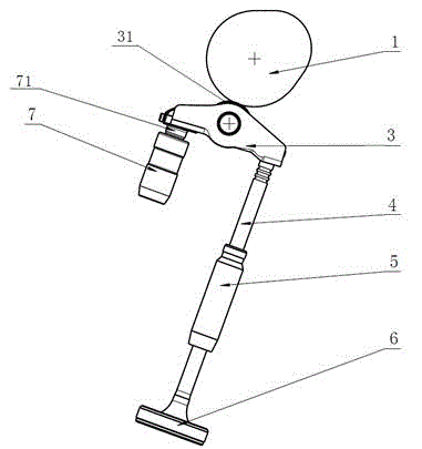
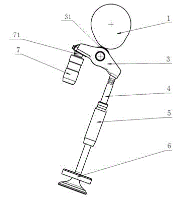
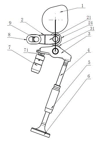
[0021] Such as image 3 , Figure 4 , Figure 5 with Image 6 The engine variable valve lift mechanism shown includes a cam 1 arranged on the camshaft, a hydraulic tappet 7 positioned and installed in the cylinder head, and a pendulum supported on the hydraulic tappet head 71 of the hydraulic tappet 7 at one end. Arm 3, the valve 4 connected to the other end of the swing arm 3, the swing arm roller 31 that is located in the middle of the swing arm 3 and opens / closes the valve by reciprocating up and down, the driving device, is connected with the driving device and slides under the drive of the driving device The slide bar 9, the bar-shaped chute member 8 that is positioned and installed in the cylinder head and cooperates with the slide bar 9, and the rocker arm 2 between the cam 1 and the swing arm 3; the rocker arm 2 is sleeved on the slide bar 9 by one end and A sup...


PUM


Abstract

The invention discloses a variable valve lift mechanism of an engine. The variable valve lift mechanism comprises a cam arranged on a cam shaft, a hydraulic tappet positioned and mounted in a cylinder cover, a swinging arm of which one end is supported on the hydraulic tappet, a valve connected with the other end of the swinging arm, a swinging arm roller arranged in the middle of the swinging arm, a driving device, a slide bar which is connected with the driving device and is driven by the driving device to slide, a bar-shaped sliding chute component which is positioned and mounted in the cylinder cover and is matched with the slide bar, and a rocker arm located between the cam and the swinging arm, wherein the rocker arm consists of a supporting seat, a roller shaft and a rocker arm roller; one end of the supporting seat sleeves the slide bar, and the supporting seat can rotate relative to the slide bar; the roller bearing is positioned and mounted at the other end of the supporting seat; the rocker arm roller is connected to the roller shaft, and can rotate in the supporting seat relative to the roller shaft; the rocker arm roller is matched with the cam and the swinging arm roller, and the rotation of the cam is transferred to the swinging arm roller. Through the adoption of the mechanism, the lift of the valve can be changed, and more ideal gas distribution is achieved. At the same time, the structure is simplified, the reliability is improved, and the cost is reduced.

Description

technical field [0001] The invention relates to an engine component, in particular to an engine variable valve lift mechanism. Background technique [0002] An automobile engine has a combustion chamber in which fuel is burned to generate power, and the combustion chamber is equipped with an intake valve for supplying gas and an exhaust valve for exhausting burned gas. The intake valve and exhaust valve open and close the combustion chamber through the valve lift device connected to the crankshaft. The opening / closing timing and lift of the intake and exhaust valves of the traditional engine are fixed. See figure 1 , figure 2 , the valve lift mechanism includes a cam 1 located on the camshaft, a hydraulic tappet 7 positioned and installed in the cylinder head, a swing arm 3 supported on the hydraulic tappet at one end, a valve 4 connected to the other end of the swing arm, and a set In the middle of the swing arm, the swing arm roller 31 that opens / closes the valve by re...

Claims


Application Information

Patent Timeline
Patent Type & Authority Applications(China)
IPC IPC(8): F01L13/00
Inventor 付秋波赵勇郑素芳郑小平彭海
Owner CHONGQING CHANGAN AUTOMOBILE CO LTD
Why Eureka
Try Eureka