Brush electronic fan drive protection system and self-diagnosis method

An electronic fan, drive protection technology, applied in engine components, machines/engines, engine cooling, etc., can solve problems such as inconvenient operation, poor heat dissipation, and inability to achieve intelligent self-fault diagnosis.

Active Publication Date: 2014-07-23
CAMALUOYANGELECTROMECHANIC
View PDF8 Cites 9 Cited by
  • Summary
  • Abstract
  • Description
  • Claims
  • Application Information

AI Technical Summary

Problems solved by technology

The engine intelligent cooling system composed of electronic fans is environmentally friendly, efficient, energy-saving, and adapts to technological trends, while the traditional mechanical fan cooling system is incomparable
However, when the electronic fans and controllers on the market fail,

Method used


Image

  • Brush electronic fan drive protection system and self-diagnosis method
  • Brush electronic fan drive protection system and self-diagnosis method
  • Brush electronic fan drive protection system and self-diagnosis method

Examples


Embodiment 1

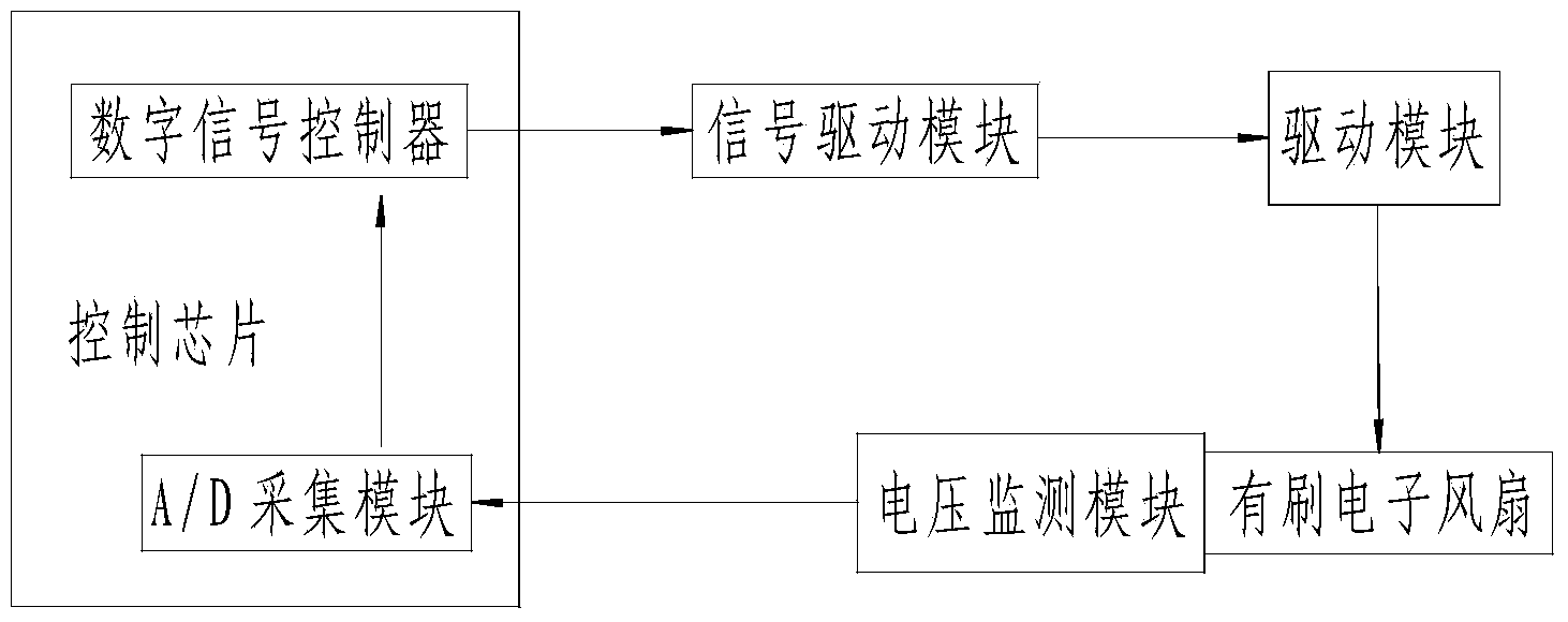
[0028] A signal drive module is set between the control chip and the drive module, lines are set between the signal drive module and the control chip and the drive module, a brushed electronic fan is set between the drive module and the voltage monitoring module, and a brushed electronic fan is set between the drive module and the brushed electronic fan. The circuit is set; an A / D acquisition module and a digital signal controller are set in the control chip, an A / D acquisition channel is set between the A / D acquisition module and the digital signal controller, and an A / D acquisition channel is set between the A / D acquisition module and the voltage monitoring module A line is set between the digital signal controller and a signal driving module.

Embodiment 2

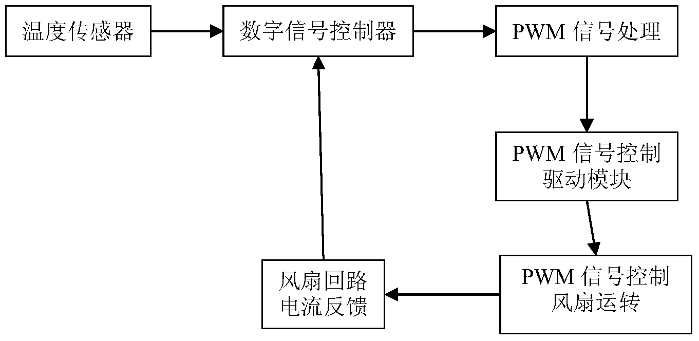
[0030] The system program is initialized, and then the alarm is checked. If there is any abnormality, it will enter the alarm processing program. If there is no abnormality, continue. According to the temperature of the engine water tank detected by the temperature sensor, set the temperature of the engine water tank when the fan is started. When the temperature value T of the engine water tank detected by the temperature sensor is less than the opening temperature, the single cycle of the output code ends. When T>=the opening temperature, the fan is started according to the preset; after the temperature sensor converts the temperature of the engine water tank into a digital signal, It is transmitted to the digital signal controller, compared and calculated according to the software setting value, and a PWM signal is generated according to the position where the fan needs to be turned on and the required speed. When the PWM control signal is 0, the drive module is turned off, an...

Embodiment 3

[0032] The fan disconnection diagnostic program is as follows: when the PWM control signal is greater than or equal to X, X is set to a value between 10% and 100% according to the specific system, and the current monitoring module detects that V2 is less than or equal to V0+A, and A is the setting Error, after the digital signal controller detects the same signal PWM>=X and V2<=V0+A for many times, it will immediately send an alarm signal to realize the fan circuit breaker diagnosis; when the PWM control signal is less than X, or V2 is greater than V0+A , the output code single cycle ends.


PUM


Abstract

The invention relates to a brush electronic fan drive protection system and a self-diagnosis method. The brush electronic fan drive protection system is composed of a control chip, a signal drive module, a drive module, a brush electronic fan, a voltage monitoring module, an A/D collection module and a digital signal controller. The functions of power-on self-inspection for a system, real-time state detection, self-diagnosis for faults and classification and display for faults can be achieved, the fan is automatically driven to run at variable speed by a set program, the voltage monitoring module can achieve on-off control over the brush electronic fan, adjustment of running speed, open circuit and short circuit protection for the fan, and achieve various protection in cooperation with the program.

Description

[0001] technical field [0002] The invention relates to the technical field of engine intelligent cooling system (ATS), in particular to a brushed electronic fan drive protection system and a self-diagnosis method. [0003] Background technique [0004] At present, the engine thermal management system in the domestic automobile industry has been over-controlled from traditional mechanical fans to electronic fans. Among them, the car industry has been initially completed, while the urban public transport and tourist passenger transportation industries are steadily advancing. The engine intelligent cooling system composed of electronic fans is environmentally friendly, efficient, energy-saving, and adapts to technological trends, while the traditional mechanical fan cooling system is incomparable. However, when the electronic fans and controllers on the market fail, professionals with extremely high professional knowledge are required to detect and repair them. [0005] T...

Claims


Application Information

Patent Timeline
IPC IPC(8): F04D27/00F01P5/02
Inventor 严世宝韩国峰王凤魁张向芽
Owner CAMALUOYANGELECTROMECHANIC
Why Eureka
Try Eureka