Floating ball self-sucking valve with lever structure and design method thereof

A self-priming valve, floating ball technology, applied in the direction of the float, valve details, valve device and other directions of the control valve, can solve the problems of poor cavitation performance, poor sealing, low pump efficiency, etc., to improve performance and operational reliability, The effect of improving service life and reducing leakage loss

Active Publication Date: 2014-07-23
JIANGSU UNIV
View PDF4 Cites 6 Cited by
  • Summary
  • Abstract
  • Description
  • Claims
  • Application Information

AI Technical Summary

Problems solved by technology

[0003] General self-priming pumps do not have special self-priming devices, such as internal mixing and external mixing self-priming pumps. Due to the backflow holes, liquid storage chambers, etc., the pump efficiency of this type of self-priming pump is low and the cavitation performance is also poor worse
For self-priming pumps with special self-priming devices, the self-priming valves are generally rubber steel ball valves, and the rubber steel ball valves are connected to positive displacement pumps. The liquid enters the positive displacement pump for suction, which affects the normal operation of the water pump and reduces pump efficiency and cavitation performance
Therefore, for a self-priming pump with a self-priming device, its self-priming performance and vacuum are largely determined by the self-priming valve, and the design of the self-priming valve plays a key role in the design of the self-priming performance of the entire self-priming pump , but at present, the design method of the self-priming valve system of this type of self-priming pump is lacking

Method used


Image

  • Floating ball self-sucking valve with lever structure and design method thereof
  • Floating ball self-sucking valve with lever structure and design method thereof
  • Floating ball self-sucking valve with lever structure and design method thereof

Examples


Embodiment Construction

[0033] The present invention will be further described below in conjunction with the accompanying drawings and specific embodiments, but the protection scope of the present invention is not limited thereto.

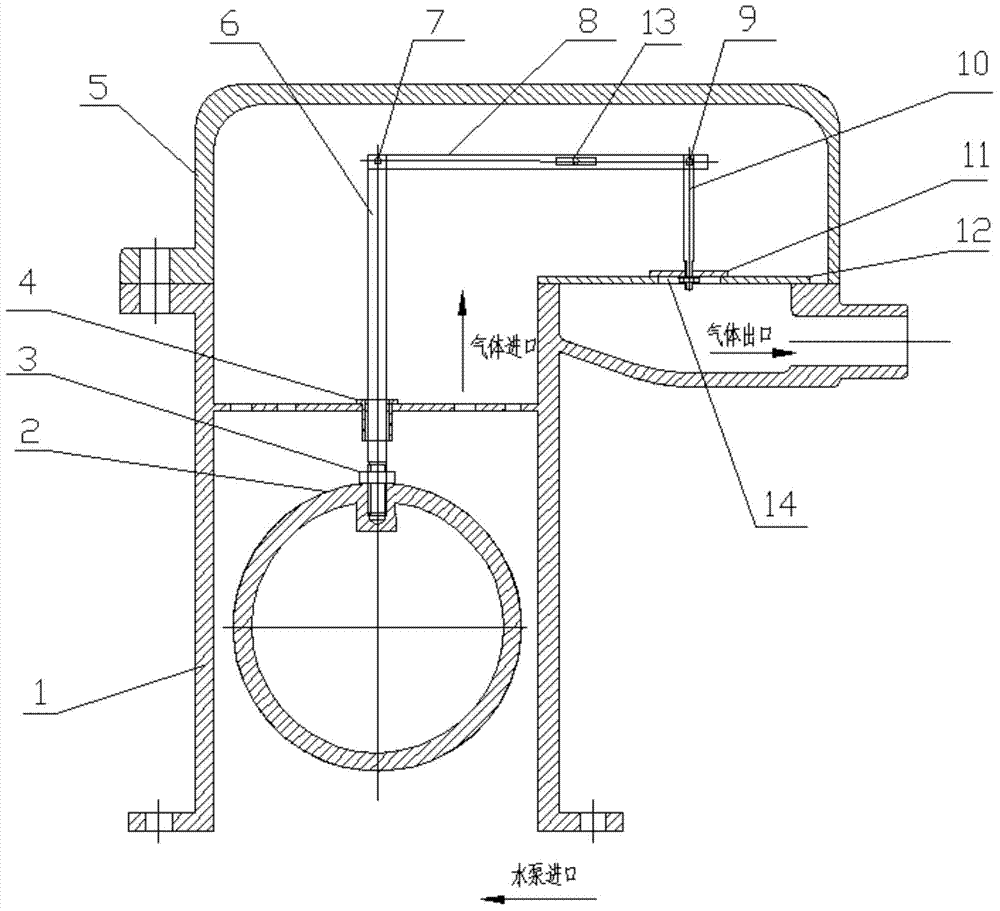
[0034] Such as figure 1 As shown, the floating ball self-priming valve with lever structure according to the present invention includes a valve body 1 and a hollow floating ball 2. The valve body 1 is provided with an air outlet perpendicular to it, and the upper opening of the air outlet, And be provided with an air valve port cover 12; The hollow floating ball 2 is connected with one end of the ejector rod 6 through the floating ball fastening nut 3, and the ejector rod 6 passes through the ejector rod movable pipe 4 fixed on the valve body 1, The other end of the ejector rod 6 is connected with the valve rod 10 through a lever 8 , and the lever fulcrum 13 of the lever 8 is fixed on the side wall of the valve body cover 5 . The ratio of the length of the power arm of t...


PUM


Abstract

The invention provides a floating ball self-sucking valve with a lever structure and a design method of the floating ball self-sucking valve with the lever structure. The self-sucking valve comprises a valve body and a hollow floating ball. The self-sucking valve is characterized in that an air outlet perpendicular to the valve body is formed in the valve body, and the upper portion of the air outlet is open and is provided with a valve port cover; the hollow floating ball is connected with one end of an ejector rod through a floating ball fastening nut, the ejector rod penetrates through an ejector rod movable tube fixed to the valve body, the other end of the ejector rod is connected with a valve rod through a lever arranged on the side wall of a valve body cover, and a sealing rubber ring is fixed to the valve rod and located at the position of a valve hole of the valve port cover. According to the floating ball self-sucking valve with the lever structure, the acting force exerted when the floating ball self-sucking valve is closed is large, the reliability of the sealing performance of the valve is improved, the amount of leaked liquid, entering a displacement pump, of the self-sucking valve at the position of an inlet of the self-sucking pump is reduced, the operating efficiency and the reliability of the suction displacement pump are improved, and the pumping efficiency and the cavitation performance are improved.

Description

technical field [0001] The invention relates to a self-priming pump, in particular to a floating ball self-priming valve with a lever structure and a design method thereof. Background technique [0002] Self-priming pump is a special kind of centrifugal pump, which means that before starting for the first time, only a certain amount of water needs to be added to the pump body, and there is no need to fill the water inlet pipe with water. A class of water pumps that work properly. It has the advantages of convenient use and reliable operation. [0003] General self-priming pumps do not have special self-priming devices, such as internal mixing and external mixing self-priming pumps. Due to the backflow holes, liquid storage chambers, etc., the pump efficiency of this type of self-priming pump is low and the cavitation performance is also poor worse. For self-priming pumps with special self-priming devices, the self-priming valves are generally rubber steel ball valves, and...

Claims


Application Information

Patent Timeline
Patent Type & Authority Applications(China)
IPC IPC(8): F16K31/22F16K33/00
CPCF16K31/22F16K33/00
Inventor 付强朱荣生王秀礼张帆
Owner JIANGSU UNIV
Why Eureka
Try Eureka