Universal vector photographing and video recording support

A technology of camera support and vector, which is applied in the direction of machine platform/support, supporting machine, mechanical equipment, etc. It can solve the problems of long adjustment time, troublesome lifting position, and inability to share multiple positions, and achieve the effect of flexible angle change

Inactive Publication Date: 2014-07-23
李戈
View PDF8 Cites 6 Cited by
  • Summary
  • Abstract
  • Description
  • Claims
  • Application Information

AI Technical Summary

Problems solved by technology

The disadvantages of the tripod are: ①It is troublesome to move; ②It needs to be re-calibrated after moving; ③It is troublesome to lift the position; ④It cannot be shared by multiple cameras
[0004] The monopod is supported by independent legs. This monopod effectively solves the trouble of moving and lifting, but it still has the following disadvantages: ①It cannot work independently and must be held by humans; human operation cannot work for a long time, so it is necessary for long-term shooting Difficult to meet; ② cannot share multiple cameras
[0005] The patent with the notification number CN2213907Y discloses a multi-directional free-moving universal camera frame, which can move freely in multiple directions, but every time it is adjusted, it is necessary to tighten or loosen the hand wheel once, and its operation is troublesome. It takes a long time to adjust; and the lens pointing of the patent has changed after moving the camera position, and the pointing angle of the lens needs to be readjusted

Method used


Image

  • Universal vector photographing and video recording support
  • Universal vector photographing and video recording support
  • Universal vector photographing and video recording support

Examples


Embodiment 1

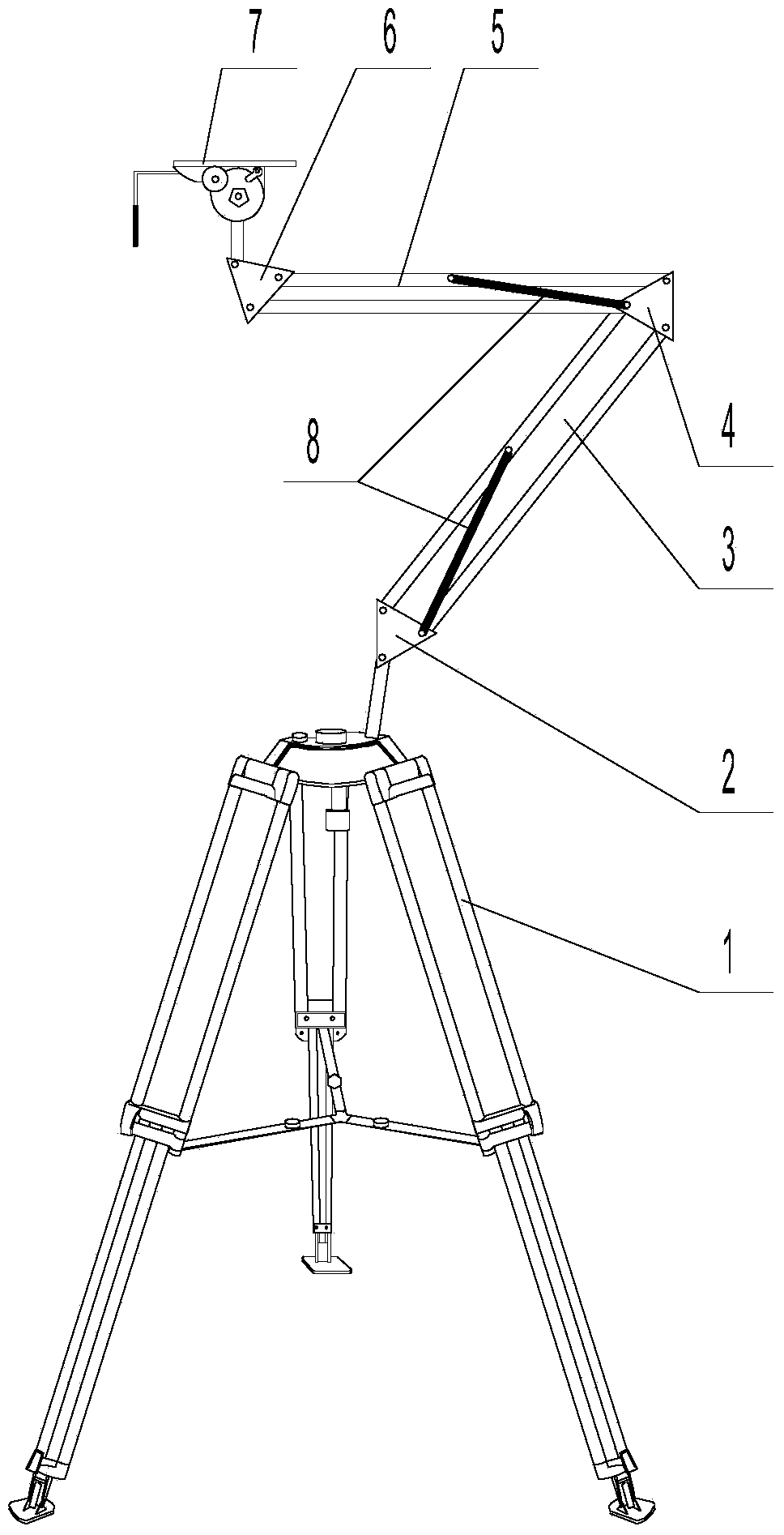
[0035] figure 1 Disclosed in is a kind of universal vector photographic camera bracket, comprising a shooting support device 1, a lower mechanical arm 3, an upper machine 5, and a pan-tilt tray 7. The shooting support device 1 is a tripod, and the top of the shooting support device 1 Connecting seat A2 is detachably connected by a fastener, and the bottom of the pan-tilt tray 7 is detachably connected to a connecting seat C6 by a fastener; the bottom end of the lower mechanical arm 3 is hinged with the connecting seat A2, and the lower mechanical arm The top of 3 is hinged with the bottom end of upper mechanical arm 5 through connecting seat B4, and the top of upper mechanical arm 5 is hinged with connecting seat C6.

[0036] The upper mechanical arm 3 and the lower mechanical arm 5 are both composed of two parallel pipe arms, and the two ends of the two parallel pipe arms of the lower mechanical arm 3 are respectively hinged with the connecting seat A2 and the connecting seat...

Embodiment 2

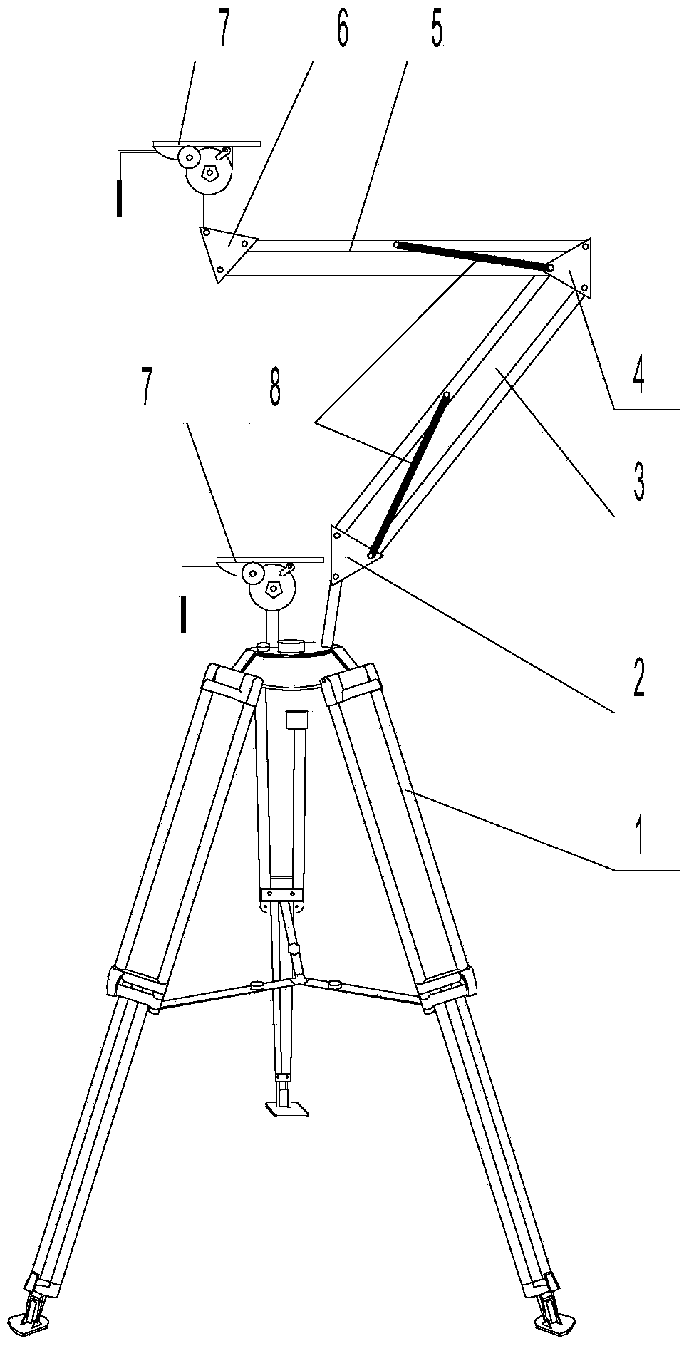
[0040] figure 2 What is disclosed in is a universal vector photography camera bracket with two camera positions. The basic structure of the bracket is the same as that of Embodiment 1, the difference is that: the top of the tripod used as the shooting support device 1 is also connected with a cloud platform Tray 7, the structure of this universal vector photography camera bracket is as follows:

[0041] A kind of universal vector photographic camera bracket, comprising a shooting support device 1, a lower mechanical arm 3, an upper machine 5, and a pan-tilt tray 7. The shooting support device 1 is a tripod, and the top of the shooting support device 1 is passed through a fastener The connecting seat A2 is detachably connected, and the bottom of the pan-tilt tray 7 is detachably connected with the connecting seat C6 through fasteners; the bottom end of the lower mechanical arm 3 is hinged with the connecting seat A2, and the top end of the lower mechanical arm 3 is The connec...

Embodiment 3

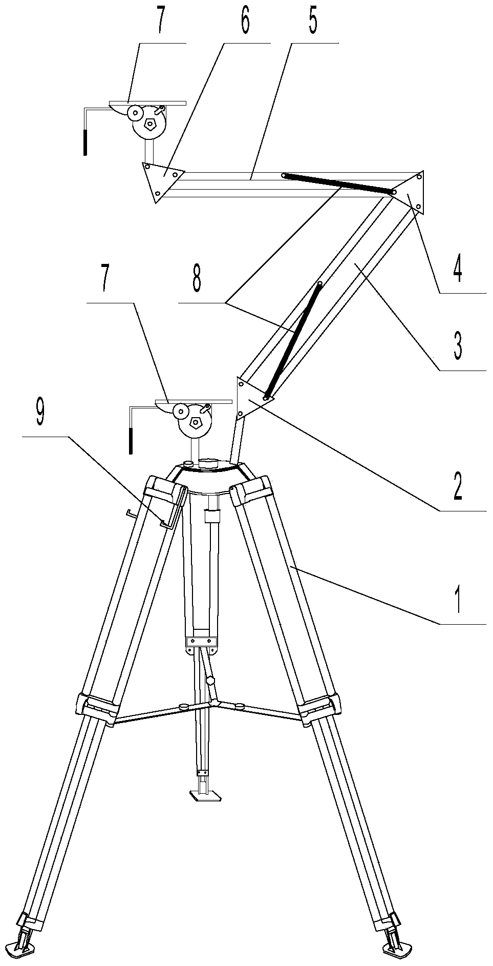
[0045] image 3 Disclosed in is another kind of universal vector photographic camera bracket, the basic structure of this bracket is the same as that of Embodiment 2, the difference is that: the top of the tripod as the shooting support device 1 is also connected with a viewfinder placement platform 9 , the structure of the universal vector photography camera bracket is as follows:

[0046] A kind of universal vector photographic camera bracket, comprising a shooting support device 1, a lower mechanical arm 3, an upper machine 5, and a pan-tilt tray 7. The shooting support device 1 is a tripod, and the top of the shooting support device 1 is passed through a fastener The connecting seat A2 is detachably connected, and the bottom of the pan-tilt tray 7 is detachably connected with the connecting seat C6 through fasteners; the bottom end of the lower mechanical arm 3 is hinged with the connecting seat A2, and the top end of the lower mechanical arm 3 is The connecting seat B4 i...


PUM


Abstract

The invention discloses a universal vector photographing and video recording support and relates to a photographing and video recording support. The universal vector photographing and video recording support comprises a shooting supporting device, a lower mechanical arm, an upper mechanical arm and a pan-tilt tray. A connecting seat A is connected to the top of the shooting supporting device. A connecting seat C is connected to the bottom of the pan-tilt tray. The upper mechanical arm and the lower mechanical arm are respectively composed of two parallel pipe arms. The two ends of the pipe arms of the lower mechanical arm are hinged to the connecting seat A and a connecting seat B respectively to form a parallel four-bar mechanism. The two ends of the pipe arms of the upper mechanical arm are hinged to the connecting seat B and the connecting seat C respectively to form a parallel four-bar mechanism. A tensile spring is connected between the connecting seat A and the middle position of the pipe arms of the lower mechanical arm. A tensile spring is connected between the connecting seat B and the middle position of the pipe arms of the upper mechanical arm. The tensile force of each tensile spring ranges from 5 KG to 20 KG. The pan-tilt tray and a view finder carrying table are further connected to the top of the shooting supporting device. According to the universal vector photographing and video recording support, a camera can be moved quickly at will, angle change is flexible, the pointing direction of a lens is not changed after the camera is moved, the camera can be used at two positions at the same time, and the application range of the universal vector photographing and video recording support is wide.

Description

technical field [0001] The invention relates to a photographic camera stand, in particular to a universal vector photographic camera stand. Background technique [0002] Existing photographic camera supports are divided into tripods and monopods, wherein: [0003] The tripod is based on the three supporting legs, and the height is stretched, and it cooperates with the head to form the left and right rotation of the camera position and the change of the pitch angle. The disadvantages of the tripod are: ①It is troublesome to move; ②It needs to be re-calibrated after moving; ③It is troublesome to lift the position; ④It cannot be shared by multiple cameras. [0004] The monopod is supported by independent legs. This monopod effectively solves the trouble of moving and lifting, but it still has the following disadvantages: ①It cannot work independently and must be held by humans; human operation cannot work for a long time, so it is necessary for long-term shooting Difficult to...

Claims


Application Information

Patent Timeline
Patent Type & Authority Applications(China)
IPC IPC(8): F16M11/12F16M11/32
Inventor 李戈覃英春何立云李柏霖
Owner 李戈
Why Eureka
Try Eureka