Ultra-thin heat pipe and manufacturing method thereof

A technology of ultra-thin heat pipes and manufacturing methods, which is applied in the field of heat pipes, and can solve the problems that copper wire mesh is not easy to adhere to the copper pipe wall, the effect is not good, and it is not easy to form high-power ultra-thin heat pipes.

Active Publication Date: 2014-07-23
ZHONGSHAN WEIQIANG TECH
View PDF8 Cites 11 Cited by
  • Summary
  • Abstract
  • Description
  • Claims
  • Application Information

AI Technical Summary

Problems solved by technology

[0003] Due to the poor effect of the copper pipe + copper wire mesh used in the past, the copper wire mesh is not easy to stick to the copper pipe wall, so the spring coil is often used to force the copper wire mesh to stick to the copper pipe wall (such as JP2012-2417) or Copper tube (with grooves) + copper wire mesh + copper powder sintering (such as CN1815131A or US2006 / 0196641A), because the copper wire mesh is covered with the copper tube wall, so it is not easy to form a high-power ultra-thin heat pipe, and The previous proposals of using copper powder sintering to form ultra-thin heat pipes (such as CN101581548A and CN102538528A) the heat pipes formed meet the extremely strict specification requirements of current tablet computers (the thickness of the heat pipe is 0.6-1.0mm, and the conduction power must not be reduced), Ultra-thin heat pipes suitable for the past specifications are no longer applicable, so new structures and processes must be used to meet increasingly stringent customer requirements

Method used


Image

  • Ultra-thin heat pipe and manufacturing method thereof
  • Ultra-thin heat pipe and manufacturing method thereof
  • Ultra-thin heat pipe and manufacturing method thereof

Examples


Embodiment Construction

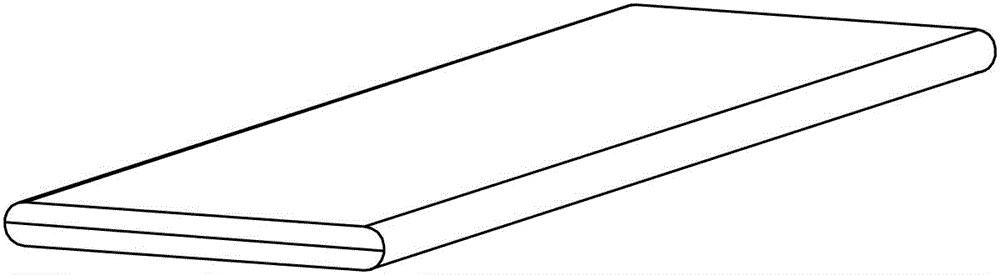
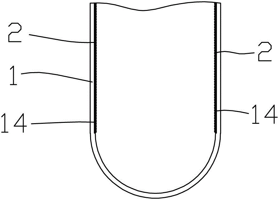
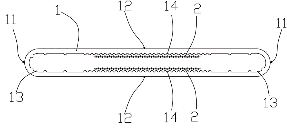
[0052] refer to Figure 1 to Figure 3 , what the above figure shows is one of the preferred embodiments of the present invention, the ultra-thin heat pipe mainly includes a flat tube body 1 in this embodiment, and the flat tube body 1 is formed into a flat shape by pressing a copper round tube, so that Two compression parts 11 symmetrical to the left and right sides and two flat parts 12 symmetrical to the upper and lower sides are formed; both ends of the pipe body are sealed, and the two ends of the seal cooperate with the wall surface of the pipe body to form a closed inner cavity, which is sealed Filled with working fluid, such as water, alcohol, coolant or other liquids.

[0053]In addition, a first groove part 13 and a second groove part 14 are also provided in the sealed inner cavity, wherein the position of the first groove part 13 corresponds to the compression part 11 outside the flat tubular body 1, and is formed along the The plurality of grooves extending in the ...


PUM


Abstract

The invention discloses an ultra-thin heat pipe. The ultra-thin heat pipe comprises a pipe body which is pressed to be in a flat shape, and the pipe body is provided with a compressed section and a smooth section. The two ends of the pipe body are sealed to form a closed inner cavity. The closed inner cavity is filled with working fluid, a first groove portion and a second groove portion are formed in the closed inner cavity of the pipe body, and a powder sintering portion adheres onto the second groove portion. The groove density of the first groove portion is lower than the groove density of the second groove portion, a metal net adheres onto the second groove portion, and the metal net and the second groove portion are combined together through sintering. The invention further provides a manufacturing method of the ultra-thin heat pipe. The size of the ultra-thin heat pipe can be manufactured to be as small as possible, meanwhile, the ultra-thin heat pipe can guarantee good heat conduction efficiency and stability, and the matched manufacturing method of the ultra-thin heat pipe is provided; the ultra-thin heat pipe and the manufacturing method of the ultra-thin heat pipe are applicable to various fields where good heat dissipation is needed and the size is limited.

Description

technical field [0001] The invention relates to a heat pipe, in particular to an ultra-thin heat pipe and a manufacturing method thereof. Background technique [0002] Because of its ultra-high heat conduction efficiency, heat pipes are widely used in various fields that require good heat dissipation. The conventional heat pipe structure is mainly a closed metal tube with a capillary structure inside the tube and injected with an appropriate amount of working fluid. When used with the evaporating end, the heat of the evaporating end is transferred to one end of the heat pipe, and the working fluid in the tube absorbs heat and vaporizes. Under the action of pressure difference, the steam flows to the other end at high speed, releases heat to the condensing end and condenses, and the condensed liquid uses the capillary structure to return from the condensing end to the evaporating end under capillary action. The end is transmitted to the condensation end to achieve the purpos...

Claims


Application Information

Patent Timeline
Patent Type & Authority Applications(China)
IPC IPC(8): F28D15/04
Inventor 陈其亮高媛媛曾新平
Owner ZHONGSHAN WEIQIANG TECH
Why Eureka
Try Eureka