
Checking method based on vibration positioning GIS partial discharge equipment

A partial discharge and calibration technology, applied in the direction of measuring electrical variables, measuring devices, instruments, etc., can solve problems such as inability to respond quickly and lack of national standards

Inactive Publication Date: 2014-07-23
BEIJING UNIV OF TECH
View PDF5 Cites 2 Cited by
  • Summary
  • Abstract
  • Description
  • Claims
  • Application Information

AI Technical Summary

Problems solved by technology

[0004] However, the calibration of this type of testing equipment is rarely involved in China, and there is no corresponding national standard, especially after the manufacturer orders the testing and positioning equipment, in order to calibrate the equipment, it is impossible to quickly respond to this problem

Method used


Image

  • Checking method based on vibration positioning GIS partial discharge equipment
  • Checking method based on vibration positioning GIS partial discharge equipment
  • Checking method based on vibration positioning GIS partial discharge equipment

Examples


Embodiment Construction

[0022] The present invention is described in detail below:

[0023] The present invention needs to complete operation according to the following steps:

[0024] Step 1: Cavity Preparation for Partial Discharge Generation

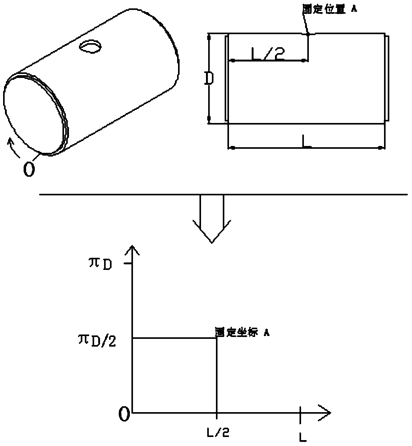
[0025] Make a two-dimensional plane of the cylindrical cavity used for checking by using the generation method, and set the coordinate system, as shown in the attached figure 1

[0026] Step 2: Standard Vibration Signal Generator Placement

[0027] The standard vibration signal generator is placed at the opening of the cylindrical cavity to simulate the vibration signal caused by the shock wave signal generated by the partial discharge. The coordinates of the vibration signal generator are fixed and marked in the developed coordinate system.

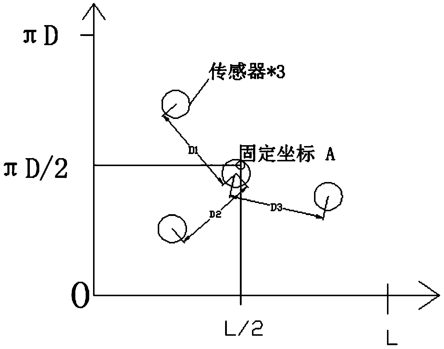
[0028] Step 3: Randomly attach the sensors of the GIS partial discharge detection equipment to be tested to the outer wall of the cylindrical cavity. figure 2 .

[0029] Step 4: Let the vibration signal generator...


PUM


Abstract

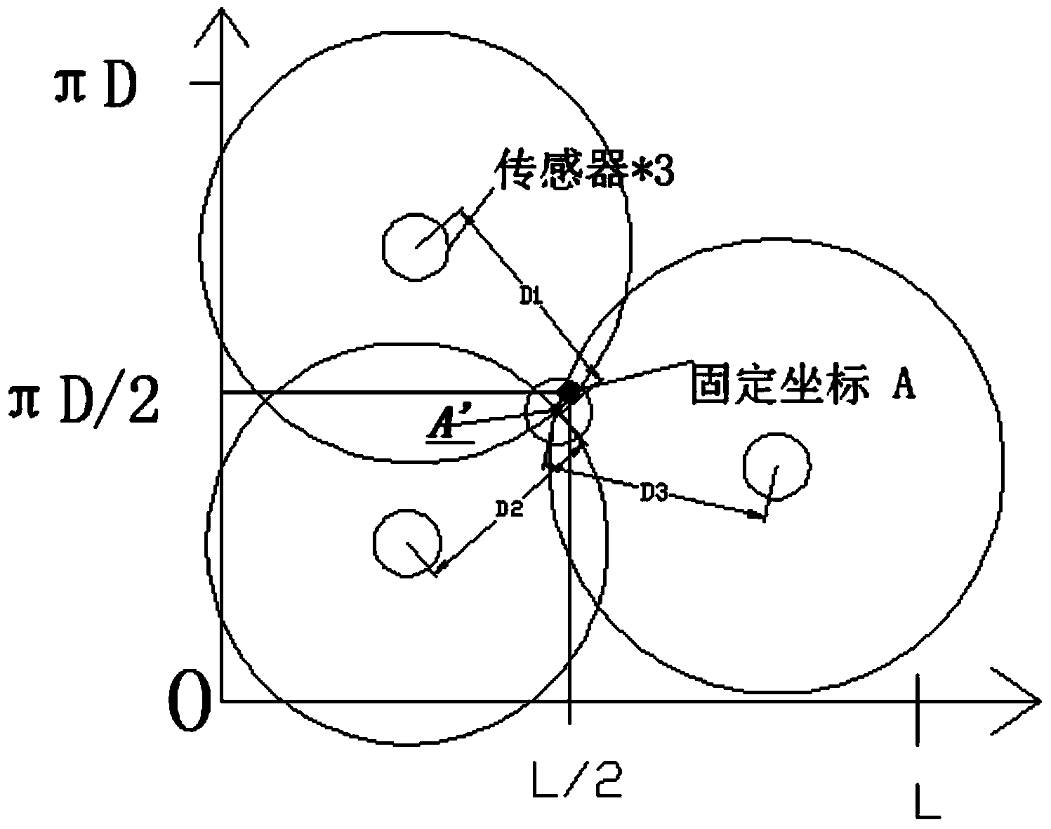
The invention provides a checking method based on vibration positioning GIS partial discharge equipment. The method is characterized in that a device is composed of following component of (1) a cylindrical cavity used for experiment and provided with a fixing hole, (2) a standard vibration signal generator, and (3) a to-be-checked detection device based on the vibration positioning GIS partial discharge equipment. The used method comprises the steps of firstly, using a generating method for converting coordinates of the cylindrical cavity into plane coordinates, marking points A of the coordinates like the attached map 1, secondly, utilizing the to-be-measured partial discharge positioning equipment for solving partial discharge coordinates, thirdly, repeatedly executing the step two, fourthly, solving mean values A' of the solved multiple sets of coordinates, comparing the mean values A' with the points A of the coordinates, and performing checking and debugging until the testing range is within a circle with the points A as the circle center and the radius of 10 cm. According to the method, the checking speed is high, a large amount of manpower and a large number of material resources can be saved, and the method plays an obvious role in checking of a production enterprise in the GIS partial discharge equipment.

Description

technical field [0001] The invention belongs to the field of power supply system detection, and in particular relates to a method for checking and locating GIS partial discharge equipment. Background technique [0002] Gas-insulated metal-enclosed switchgear (Gas Insulated Substation: GIS), as the mainstream electrical equipment widely used at present, has a history of more than 50 years since it appeared in the mid-1960s. SF6 gas is mostly used as the insulating medium inside GIS pipelines, and all high-voltage components are sealed in grounded metal cylinders. Compared with traditional open equipment, GIS has compact structure, small footprint, low noise, no fire hazard, and easy maintenance. The cycle is long, the operating mechanism is oil-free and gas-free, and has the characteristics of high operational reliability. Since the 1980s, GIS has been widely used in my country, especially in the construction and transformation of urban power grids in recent years. GIS equipme...

Claims


Application Information

Patent Timeline
Patent Type & Authority Applications(China)
IPC IPC(8): G01R35/00
Inventor 许东来李飞张文波万梦
Owner BEIJING UNIV OF TECH
Learn More