Light source system

A light source system and laser source technology, applied in the field of light source systems, can solve problems such as inability to project, low light utilization rate, and inability to accurately control the direction of light projection, so as to achieve the effect of ensuring collimation and improving accuracy

Inactive Publication Date: 2014-07-23
HONG FU JIN PRECISION IND (SHENZHEN) CO LTD +1
View PDF0 Cites 2 Cited by
  • Summary
  • Abstract
  • Description
  • Claims
  • Application Information

AI Technical Summary

Problems solved by technology

However, since the light source is generally a halogen bulb or an LED lamp, the collimation of emitted light is not good, and the projection direction of part of the light cannot be accurately controlled and cannot be projected onto the micromirror device without being utilized. Low

Method used


Image

  • Light source system
  • Light source system

Examples


Embodiment Construction

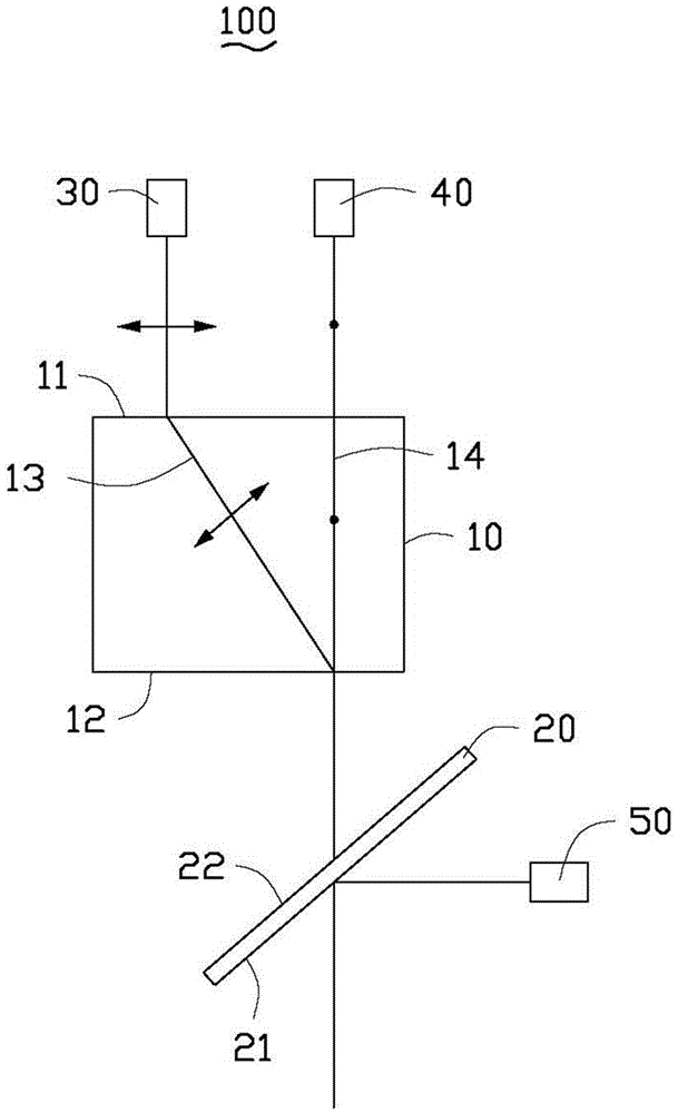
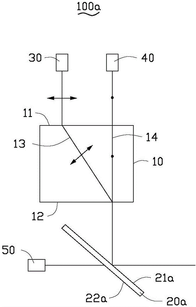
[0011] Such as figure 1 As shown, a light source system 100 provided in the first embodiment of the present invention includes a birefringent prism 10, a filter 20, a first laser source 30, a second laser source 40 and a third laser source 50 . The first color light emitted by the first laser source 30 , the second color light emitted by the second laser source 40 and the third color light emitted by the third laser source 50 synthesize white light.

[0012] The birefringent prism 10 is in the shape of a cuboid, which is made of calcite crystal. The birefringent prism 10 includes a light incident surface 11 and a light exit surface 12 parallel to the light incident surface 11 , and has a fast axis 13 and a slow axis 14 inside. The fast axis 13 and the slow axis 14 extend from the light incident surface 11 to the light exit surface 12 . The slow axis 14 is perpendicular to the light incident surface 11 and the light exit surface 12 , the fast axis 13 and the slow axis 14 int...


PUM


Abstract

The invention provides a light source system, which comprises a birefringent prism, a filter, a first laser source, a second laser source and a third laser source, wherein the birefringent prism comprises a light incoming surface and a light outgoing surface; the first laser source and the second laser source are located at the side where the light incoming surface is located; the filter is located at the side where the light outgoing surface is located; the third laser source is located at the other side opposite to one side where the filter faces the light outgoing surface; the first laser source projects a first color light line whose polarization direction is a first polarization direction; the second laser source projects a second color light line whose polarization direction is a second polarization direction; the first color light line and the second color light line pass through the light outgoing surface of the light outgoing surface, are mixed and go out in the direction vertical with the light outgoing surface; and the mixed light from the birefringent prism and a third color light line transmitted by the third laser source are transmitted and reflected via the filter and a white line is combined. Laser is adopted as light sources, and light utilization rate of light projected from the light source system can be ensured.

Description

technical field [0001] The invention relates to a light source system, in particular to a light source system using laser light as a light source. Background technique [0002] A traditional projector includes a light source, a color wheel, and a micromirror device. The light projected by the light source passes through the color wheel and then projects to the micromirror device, and the micromirror device is controlled by an image signal. The light modulates the signal light and reflects it. However, since the light source is generally a halogen bulb or an LED lamp, the collimation of emitted light is not good, and the projection direction of part of the light cannot be accurately controlled and cannot be projected onto the micromirror device without being utilized. Low. Contents of the invention [0003] In view of this, it is necessary to provide a light source system with high light utilization efficiency. [0004] A light source system includes a double refraction ...

Claims


Application Information

Patent Timeline
Patent Type & Authority Applications(China)
IPC IPC(8): G02B27/28G03B21/20F21V13/02
Inventor 陈柏洲
Owner HONG FU JIN PRECISION IND (SHENZHEN) CO LTD
Why Eureka
Try Eureka