
A method of automatically generating ied network graph

An automatic generation and network diagram technology, applied in the direction of network data retrieval, website content management, special data processing applications, etc., can solve the problem that the network layout of the display power is not fully applicable, the network layout structure varies greatly, and the satisfaction cannot be obtained. , to achieve the effect of beautiful and practical connection, beautiful and practical layout, and avoid overlapping of originals

Active Publication Date: 2017-04-19
STATE GRID CORP OF CHINA +2
View PDF8 Cites 0 Cited by
  • Summary
  • Abstract
  • Description
  • Claims
  • Application Information

AI Technical Summary

Problems solved by technology

The essence of the ray layout algorithm is the polar coordinate form of the tree layout, but as far as the layout effect is concerned, the ray layout is easier to be accepted by people
[0009] Although these layout algorithms are relatively mature, they are still not fully applicable to the network layout of display power, or they cannot reflect the characteristics of the IED network diagram well according to the logical connection.
For example: Although the tree layout algorithm is simple and efficient; but the displayed network layout is very different from the actual network structure, and satisfactory results cannot be obtained

Method used


Image

  • A method of automatically generating ied network graph
  • A method of automatically generating ied network graph
  • A method of automatically generating ied network graph

Examples


Embodiment 1

[0056] Network layout for a model that contains only one communication subnet.

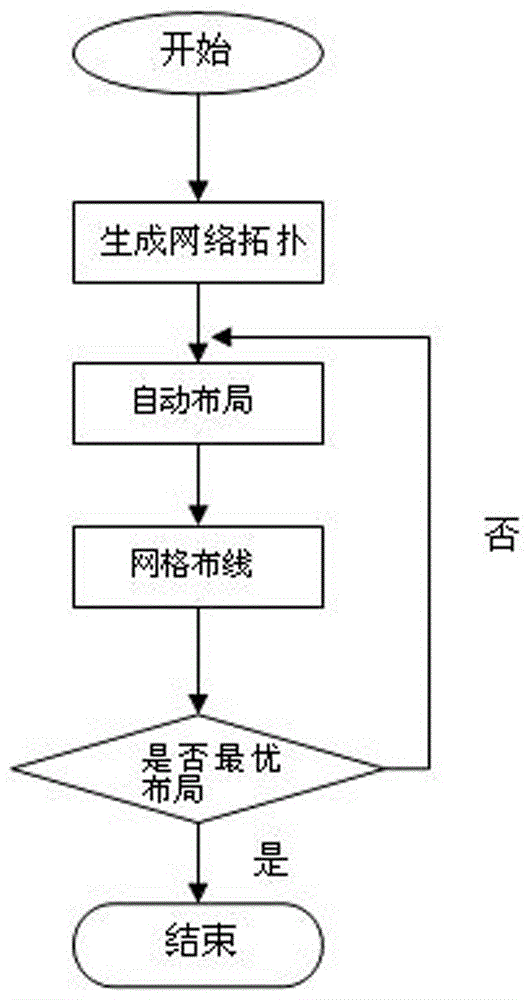
[0057] like figure 1 As shown, the method for automatically generating an IED network diagram of the present invention comprises the following steps:

[0058] Step 1: Generate the network topology:

[0059] Traverse the sub-network entries corresponding to the communication entries in the model data;

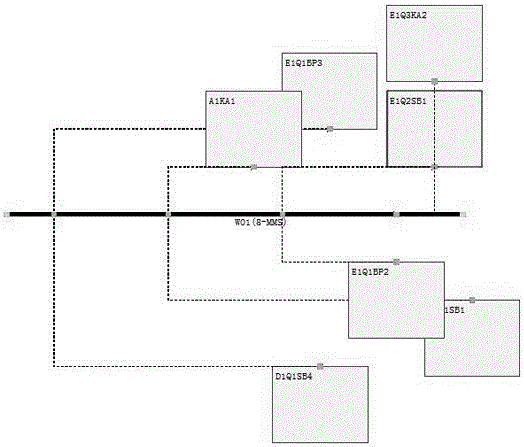
[0060] All sub-network entries are traversed, IED device layout objects are constructed, and figure 2 The network topology of the IED device layout object shown.

[0061] Step 2: Auto Layout:

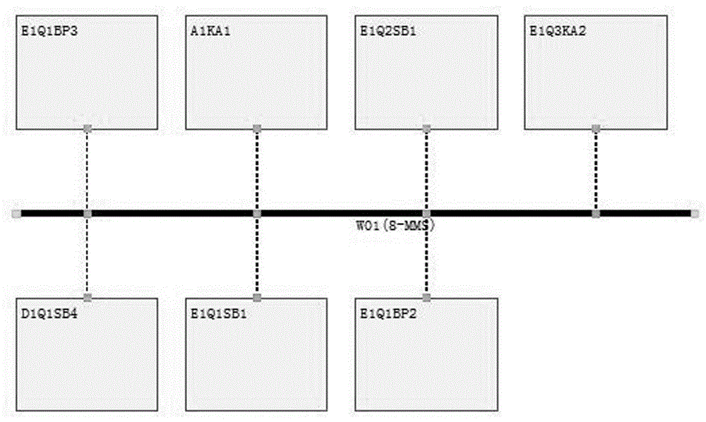
[0062] Divide the IEDs into upper and lower rows according to the number of IEDs and distribute them in the upper and lower positions of the subnet to complete the layout of the IEDs directly connected to the subnet;

[0063] Take any subnet as a unit, search within the scope of the subnet, and arrange the layout according to the search order. Every two units is a group. After this group is laid out, th...

Embodiment 2

[0077] Network layout for a model with three communication subnets.

[0078] like figure 1 As shown, the method for automatically generating an IED network diagram of the present invention comprises the following steps:

[0079] Step 1: Generate the network topology:

[0080] Traverse the sub-network entries corresponding to the communication entries in the model data;

[0081] Since there are sub-network entries that have not been traversed, the attribute network access point is searched according to the sub-network entries WO1 (8-MMS), WO12 (8-MMS) and WO13 (8-MMS), and the IED device layout object is generated and automatically generated. The network topology of the IED device layout object.

[0082] Step 2: Auto Layout:

[0083] Divide the IEDs into upper and lower rows according to the number of IEDs, and distribute them in the upper and lower positions of the subnet to complete the layout of the IEDs directly connected to the subnet.

[0084] IEDs connected to one o...


PUM


Abstract

The invention relates to a method for generating an IED network graph. The method comprises the following steps that first, a network topology is generated, wherein the network topology of an IED equipment layout object is generated according to sub-network entries corresponding to communication entries in model data; second, automatic layout is carried out, wherein IED equipment which is directly connected with a subnet is allocated first, and then grouping layout is conducted within a subnet range until the overall network layout is completed; third, grid wiring is carried out, wherein a grid reference line is set according to all graphics primitives which are completed in the second step in a layout mode, grid line cross points are traversed in all directions, and finally a connecting line path of the graphics primitives is achieved; fourth, layout examination is carried out, the layout is completed when no intersection exists, and secondary line connection is performed according to the connecting line crossed condition when intersection exists; fifth, an IED network is generated automatically, and the network graph is output. By the adoption of the method, the defect of a single algorithm is overcome, a more efficient algorithm with a reasonable logical layout can be developed according to a network graph model, the method can be adapted to different data model demands, network topology data modeling is facilitated, and the generated IED network graph is clear in line.

Description

technical field [0001] The invention relates to a method for automatically generating an IED network diagram, which is suitable for the generation of the IED network diagram of a substation automation system. Background technique [0002] Traditional network communication is described by Substation Configuration Language (SCL), and SCL is used to achieve information sharing, which lays a theoretical foundation for object-oriented system theory and the construction of general information models in the field of power systems. The IEC 61850 international standard SCL can adapt to the diversity and flexibility of equipment in the substation automation system, standardize the data information of the substation automation system, make it process power system resources with a unified and efficient standard, and provide a practical basis for the generation of network diagrams. [0003] But describing it through SCL makes it difficult for non-experts to understand and examine network...

Claims


Application Information

Patent Timeline
Patent Type & Authority Patents(China)
IPC IPC(8): G06F17/30
CPCG06F16/958
Inventor 何磊郝晓光
Owner STATE GRID CORP OF CHINA
Learn More