Supercharge Your Innovation With Domain-Expert AI Agents!

Cable vulcanization production line

A production line and cable technology, applied in the manufacture of cables/conductors, insulation of conductors/cables, electrical components, etc., can solve the problems of scratching the rubber surface, easy adhesion of dust impurities, large cable cross-section, etc., to improve product quality , Improve the effect of wrapping effect

Inactive Publication Date: 2014-07-23
罗静
View PDF0 Cites 4 Cited by
  • Summary
  • Abstract
  • Description
  • Claims
  • Application Information

AI Technical Summary

Problems solved by technology

[0005] An existing cable vulcanization production line includes a pay-off device, an extruder, a sealed water tank, a traction device, a take-up device, a catenary vulcanization tube and a bracket, and one end of the catenary vulcanization tube is fixed on the bracket , the other end is connected with the outlet seal on the sealed water tank, and the equipment is all located on the flat ground. Such a structure has the following technical problems: 1. The vulcanization pipe in the common continuous vulcanization equipment is usually a straight pipe. Considering the cross section of the cable Large and self-heavy, the cable will sag in an arc shape due to its own weight in the tube, so the cable is prone to dragging the wall in the straight tube and scratching the rubber surface
2. The cable core coming out of the pay-off device is easy to adhere to dust and impurities, and the impurities entering the extruder will easily affect the wrapping effect of the rubber insulating layer injected by the extruder on the cable core. Some cable vulcanization production lines are improved

Method used


Image

  • Cable vulcanization production line
  • Cable vulcanization production line

Examples


Embodiment 1

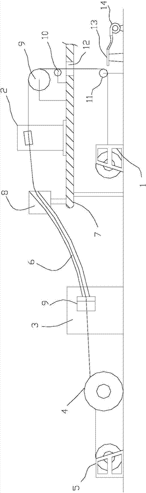
[0019] Such as figure 1 As shown, a cable vulcanization production line described in this embodiment includes a pay-off device 1, an extruder 2, a sealed water tank 3, a traction device 4, a take-up device 5, a catenary vulcanization pipe 6 and a bracket 8, One end of the catenary vulcanization tube 6 is fixed on the bracket 8, and the other end is connected with the outlet seal 9 on the sealed water tank 3; the take-up device 5 and the traction device 4 are sequentially located on the left side of the sealed water tank 3; it is characterized in that Including a platform 7, the pay-off device 1 is located below the platform 7, the support 8 and the extruder 2 are located above the platform 7, the support 8 is located on the upper right side of the sealed water tank 3, and the extruder 2 is located on the right side of the support 8. The right side of the machine 2 is provided with a first guide wheel 9, and a tensioning wheel 10 is provided below the first guide wheel 9; the r...

Embodiment 2

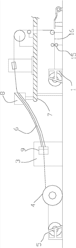
[0024] Such as figure 2 As shown, the cable vulcanization production line described in this embodiment is different from that of Embodiment 1 in that two upper and lower cleaning rollers 15 are arranged between the pay-off device 1 and the second guide wheel 11 .


PUM


Abstract

The invention discloses a cable vulcanization production line. The cable vulcanization production line comprises a pay-off device, an extruder, a seal water tank, a traction device, a take-up device, a catenary vulcanizing tube and a bracket, wherein one end of the catenary vulcanizing tube is fixed on the bracket while the other end is hermetically connected with the outlet of the seal water tank; the cable vulcanization production line further comprises a platform, the pay-off device is located under the platform, the bracket and the extruder are located above the platform, the bracket is located above the right of the seal water tank, a first guide wheel is mounted at the right side of the extruder, and a tensioning wheel is mounted under the first guide wheel; a second guide wheel is mounted at the right of the pay-off device; a blow pipe capable of blowing the cable is mounted at the right of the second guide wheel, and the blow pipe is connected with a compressed air pipe or an air pump. By means of the cable vulcanization production line, the quality of the produced cable is obviously better than that of the cable produced by the prior art, the cable surface quality is high, and the abrasion and scratch are reduced obviously.

Description

[0001] technical field [0002] The invention relates to a cable production line, in particular to a cable vulcanization production line. [0003] Background technique [0004] In cable production, there are two processes for the rubber material from extrusion to vulcanization: one is to be vulcanized in the vulcanization tank after it comes out of the extruder, which is divided into two steps; After packaging, it directly enters the vulcanization tube for vulcanization, which is continuous and complete at one time. The production process of the latter type of cable needs to be carried out on a special continuous vulcanization equipment for the production of cables. [0005] An existing cable vulcanization production line includes a pay-off device, an extruder, a sealed water tank, a traction device, a take-up device, a catenary vulcanization tube and a bracket, and one end of the catenary vulcanization tube is fixed on the bracket , the other end is connected with the ou...

Claims


Application Information

Patent Timeline
IPC IPC(8): H01B13/00H01B13/14
Inventor 罗静
Owner 罗静
Features
  • R&D
  • Intellectual Property
  • Life Sciences
  • Materials
  • Tech Scout
  • Unparalleled Data Quality
  • Higher Quality Content
  • 60% Fewer Hallucinations
Learn More