
A UWB Low Profile Printed Circularly Polarized Helical Antenna

A helical antenna, low-profile technology, applied in the antenna grounding device, antenna support/installation device, radiating element structure and other directions, can solve the problems of high antenna profile height and large input impedance, etc.

Inactive Publication Date: 2016-06-29
SHENZHEN UNIV
View PDF4 Cites 0 Cited by
  • Summary
  • Abstract
  • Description
  • Claims
  • Application Information

AI Technical Summary

Problems solved by technology

[0011] In view of the above deficiencies in the prior art, the purpose of the present invention is to provide an ultra-wideband low-profile printed circularly polarized helical antenna, which solves the problem that the input impedance of the metal wire helical antenna in the prior art is relatively large (greater than 100Ω), and it is difficult to directly Impedance matching with 50Ω excitation source, and the defect that the profile height of the antenna is large

Method used


Image

  • A UWB Low Profile Printed Circularly Polarized Helical Antenna
  • A UWB Low Profile Printed Circularly Polarized Helical Antenna
  • A UWB Low Profile Printed Circularly Polarized Helical Antenna

Examples


Embodiment Construction

[0036] The present invention provides an ultra-broadband low-profile printed circularly polarized helical antenna. In order to make the purpose, technical solution and effect of the present invention clearer and clearer, the present invention will be further described in detail below with reference to the accompanying drawings and examples. It should be understood that the specific embodiments described here are only used to explain the present invention, not to limit the present invention.

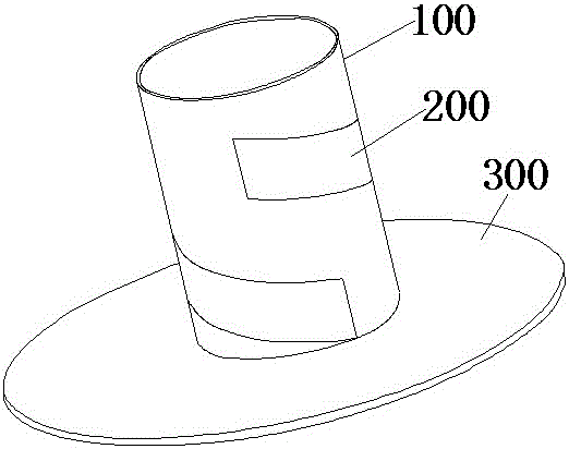
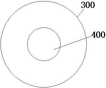
[0037] See figure 1 and figure 2 , figure 1 It is a schematic structural diagram of a preferred embodiment of the ultra-wideband low-profile printed circularly polarized helical antenna of the present invention, figure 2 It is a bottom view of a preferred embodiment of the ultra-wideband low-profile printed circularly polarized helical antenna described in the present invention. The ultra-wideband low-profile printed circularly polarized helical antenna includes:

[0038] A first die...


PUM


Abstract

The invention provides an ultra-wide-band low-profile printed-type circularly polarized spiral antenna. The ultra-wide-band low-profile printed-type circularly polarized spiral antenna comprises a first dielectric substrate set to be hollow and cylindrical, a spiral metal sheet arranged on the outer surface of the first dielectric substrate in a spirally-wounded mode, a second dielectric substrate arranged at the bottom of the first dielectric substrate and connected with the first dielectric substrate and a metal grounding plate arranged at the bottom of the second dielectric substrate, connected with the second dielectric substrate and used for grounding, wherein the cross section direction of the second dielectric substrate is perpendicular to the axial direction of the first dielectric substrate. Due to the fact that the width of the spiral metal sheet is adjustable, input impedance of the antenna can be controlled by changing the width of the metal sheet, and an ultra-wide-band impedance band width can be realized at the same time; on the basis of the low-profile feature of the antenna is maintained, the polarized radiation feature and the high-gain characteristic of an ultra-wide band are realized, and the polarized band width can be covered by the impedance band width.

Description

technical field [0001] The invention relates to the field of antennas, in particular to an ultra-wideband low-profile printed circularly polarized helical antenna. Background technique [0002] In the traditional antenna family, antennas with circularly polarized radiation characteristics include microstrip patch antennas, multi-feed point quadrifilar helical antennas (Quadrifilar Helical Antenna), planar helical antennas (Spiral Antenna) and axial mode helical antennas (Axial-Mode Helical Antenna) Wait. [0003] Among them, the circularly polarized microstrip patch antenna with a single feed point has a narrow working bandwidth (generally within 3%). [0004] The four-arm helical antenna needs to design a complex feed network to realize the multi-feed point working mode, the antenna structure is complex, and the antenna gain is small (generally below 4dBi). [0005] The planar helical antenna has the characteristics of wide frequency band and wide beam, but because it has...

Claims


Application Information

Patent Timeline
Patent Type & Authority Patents(China)
IPC IPC(8): H01Q1/38H01Q1/12H01Q1/48
Inventor 唐锡辉李瑞瑞邢兵兵裴继红
Owner SHENZHEN UNIV
Learn More