Millimeter-wave circularly-polarized array antenna and radiation body thereof

An array antenna and radiator technology, applied in the field of wireless communication, can solve the problem of complex antenna structure, and achieve the effects of simplified structure, wide bandwidth, high axial ratio, wide impedance bandwidth and axial ratio bandwidth.

Pending Publication Date: 2018-02-23
SOUTH CHINA UNIV OF TECH
View PDF5 Cites 12 Cited by
  • Summary
  • Abstract
  • Description
  • Claims
  • Application Information

AI Technical Summary

Problems solved by technology

However, due to the use of a three-layer dielectric board, the structure of the antenna becomes very complicated

Method used


Image

  • Millimeter-wave circularly-polarized array antenna and radiation body thereof
  • Millimeter-wave circularly-polarized array antenna and radiation body thereof
  • Millimeter-wave circularly-polarized array antenna and radiation body thereof

Examples


Embodiment 1

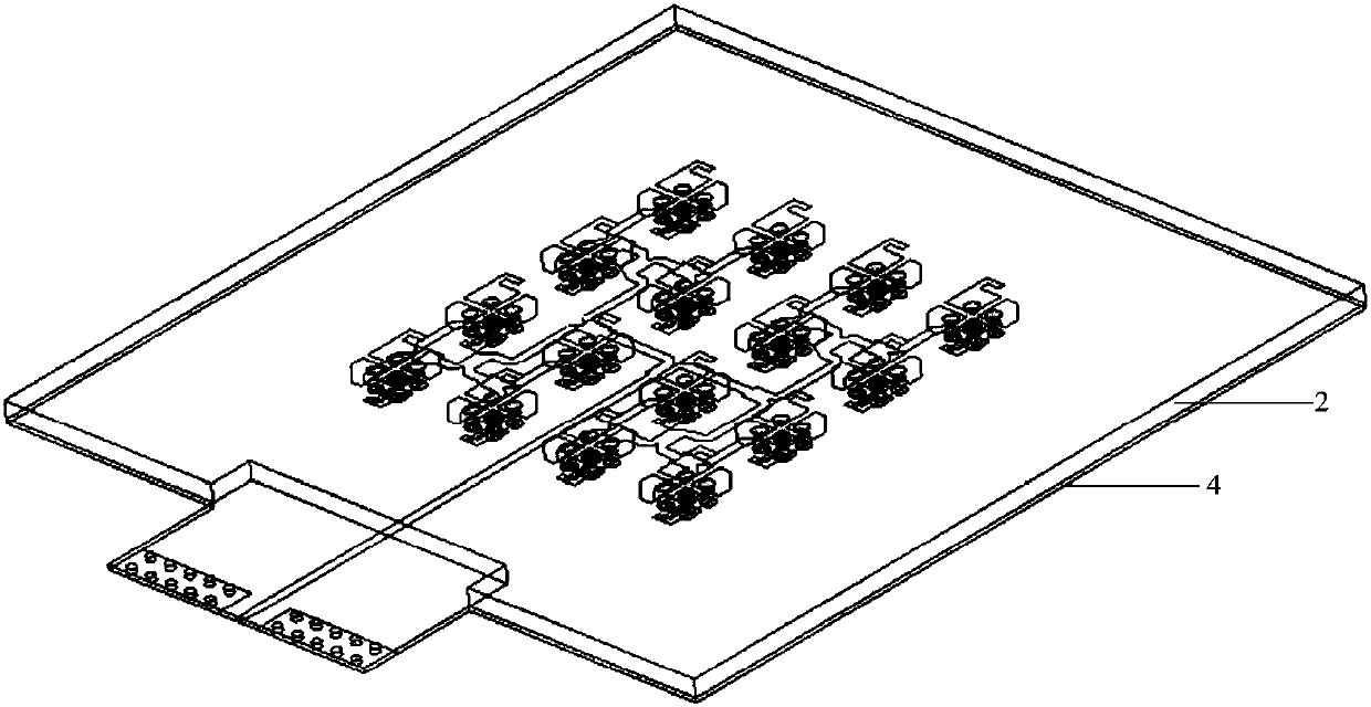
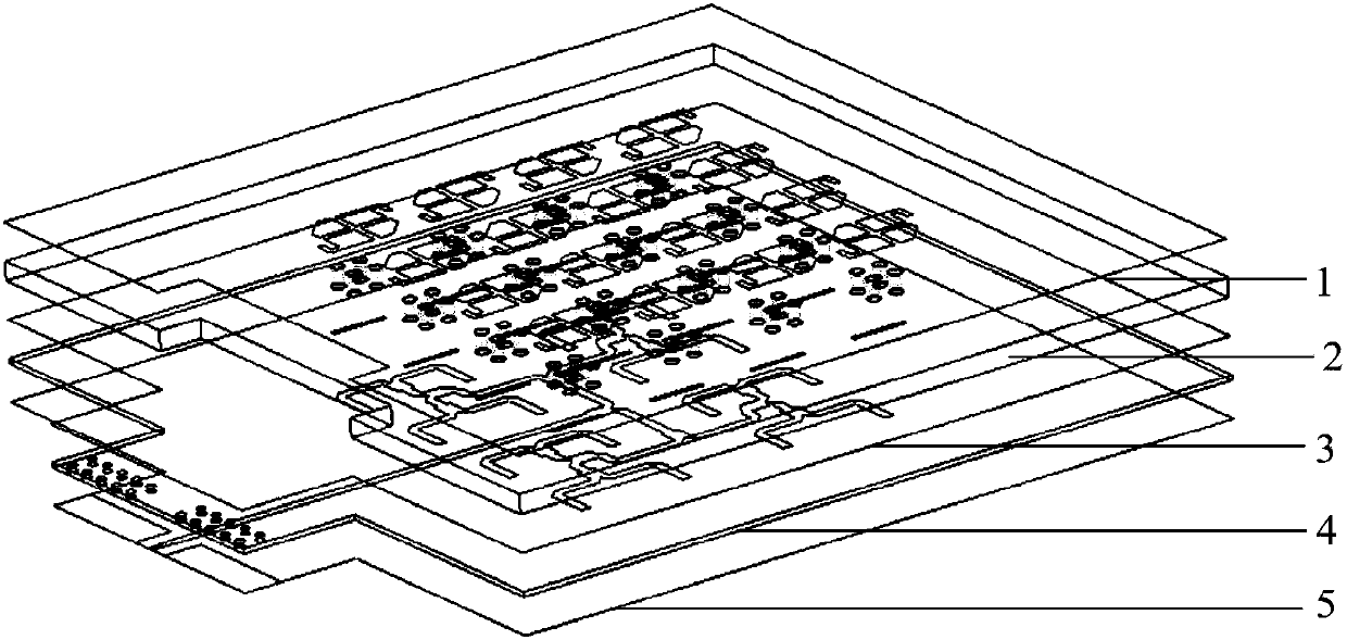
[0047] like figure 1 and figure 2 As shown, this embodiment provides a millimeter-wave circularly polarized array antenna, which is a 4*4 array antenna, which includes a radiator 1, a first dielectric substrate 2, and a first floor 3 arranged in sequence from top to bottom. , the second dielectric substrate 4 and the feed network 5, it can be seen that a five-layer structure is formed, wherein the radiator 1 is located on the first layer, the first dielectric substrate 2 is located on the first layer, the first floor 3 is located on the third layer, and the second dielectric The substrate 4 is located on the fourth floor, and the feed network 5 is located on the fifth floor.

[0048] Both the first dielectric substrate 2 and the second dielectric substrate 4 are PCB boards, but materials with different dielectric constants and different loss tangents are used. The materials can be FR-4, polyimide, polytetrafluoroethylene glass Any two of cloth and co-fired ceramics.

[004...

Embodiment 2

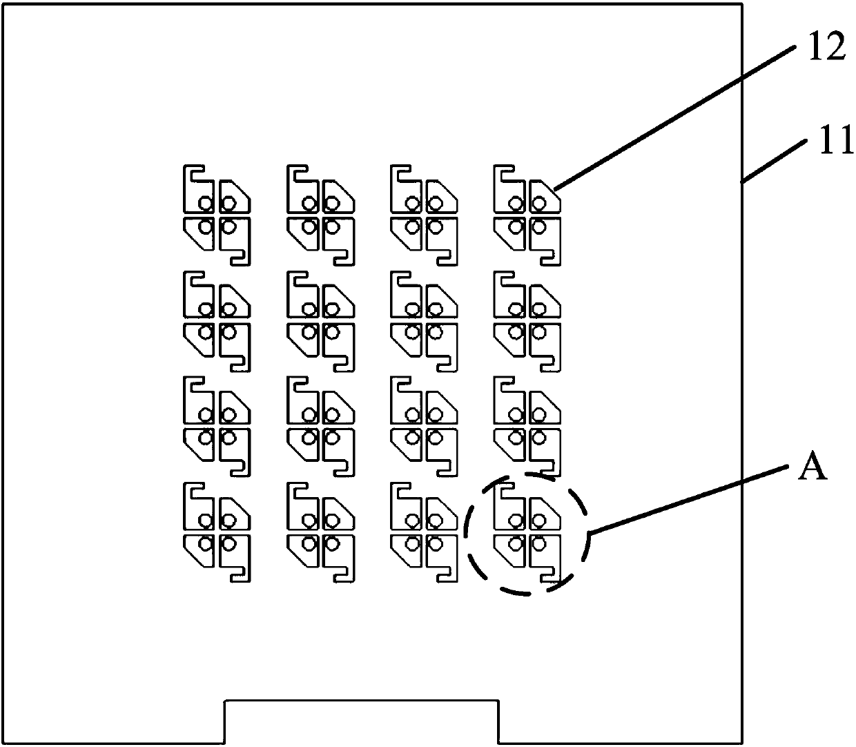
[0057] The millimeter-wave circularly polarized array antenna in this embodiment can also be a 5*5 array antenna, a 6*6 array antenna, etc., or an array antenna with different rows and columns, such as a 4*6 array antenna, a 6*8 array antenna, etc., and the radiation The numbers of units 12, slots 31 and first power dividers 52 need to be adjusted accordingly. All the other are with embodiment 1.

[0058] In summary, the millimeter-wave circularly polarized array antenna of the present invention has a longer bandwidth, a larger gain, a wider circular polarization axis ratio, and a simple structure, which can meet the requirements of the Ministry of Industry and Information Technology for mobile services in the millimeter-wave frequency band. Requirements for medium broadband wireless access systems (42.3-48.4GHz).


PUM


Abstract

The invention discloses a millimeter-wave circularly-polarized array antenna and a radiation body thereof. The antenna comprises a first dielectric substrate, a second dielectric substrate, a first floor, a feeding network and the radiation body, wherein the radiation body, the first dielectric substrate, the first floor, the second dielectric substrate and the feeding network are sequentially arranged from top to bottom, the radiation body comprises a radiation plate and a plurality of radiation units, the plurality of radiation units are arranged on the radiation plate, each radiation unit comprises four short-circuit patches, L-shaped branches are loaded at opposite corners of two of the short-circuit patches, cutting parts are arranged at opposite corners of the other short-circuit patches, and each radiation unit is connected with the first floor via a through hole in the first dielectric substrate. The millimeter-wave circularly-polarized array antenna has relatively long bandwidth, relatively large gain and relatively wide circularly-polarized shaft ratio and is simple in structure, and the requirement (42.3-48.4GHz) of a broadband wireless access system of industry and information technology planning used in millimeter-wave band mobile service can be met.

Description

technical field [0001] The invention relates to an array antenna, in particular to a millimeter-wave circularly polarized array antenna and a radiator thereof, belonging to the field of wireless communication. Background technique [0002] With the vigorous development of wireless communication technology, low-frequency electromagnetic spectrum resources are becoming increasingly exhausted. In order to meet the challenge of 5G (the 5th Generation) high-speed communication, it is necessary to develop spectrum resources in the millimeter wave band. Compared with linearly polarized antennas, circularly polarized antennas have many obvious advantages, such as anti-multipath reflection, avoiding polarization mismatch, and flexible alignment of receiving and transmitting antennas. Communication in the millimeter wave frequency band is affected by factors such as high free space transmission loss and atmospheric absorption. Therefore, millimeter wave antenna systems usually requir...

Claims


Application Information

Patent Timeline
Patent Type & Authority Applications(China)
IPC IPC(8): H01Q1/38H01Q1/48H01Q1/50H01Q21/00H01Q21/06
CPCH01Q1/38H01Q1/48H01Q1/50H01Q21/0075H01Q21/065
Inventor 涂治红甘正谢泽明
Owner SOUTH CHINA UNIV OF TECH
Why Eureka
Try Eureka