
A circularly polarized loop microstrip antenna with a curved stub ground plane

A technology of microstrip antennas and stubs, applied in the direction of electrical short antennas, antenna grounding devices, antennas suitable for movable objects, etc., can solve the problems of poor antenna bandwidth and achieve a compact structure

Active Publication Date: 2020-05-01
JILIN UNIV
View PDF10 Cites 0 Cited by
  • Summary
  • Abstract
  • Description
  • Claims
  • Application Information

AI Technical Summary

Problems solved by technology

But for single-point feeding, the antenna bandwidth is significantly worse when the size is small

Method used


Image

  • A circularly polarized loop microstrip antenna with a curved stub ground plane
  • A circularly polarized loop microstrip antenna with a curved stub ground plane
  • A circularly polarized loop microstrip antenna with a curved stub ground plane

Examples


Embodiment 1

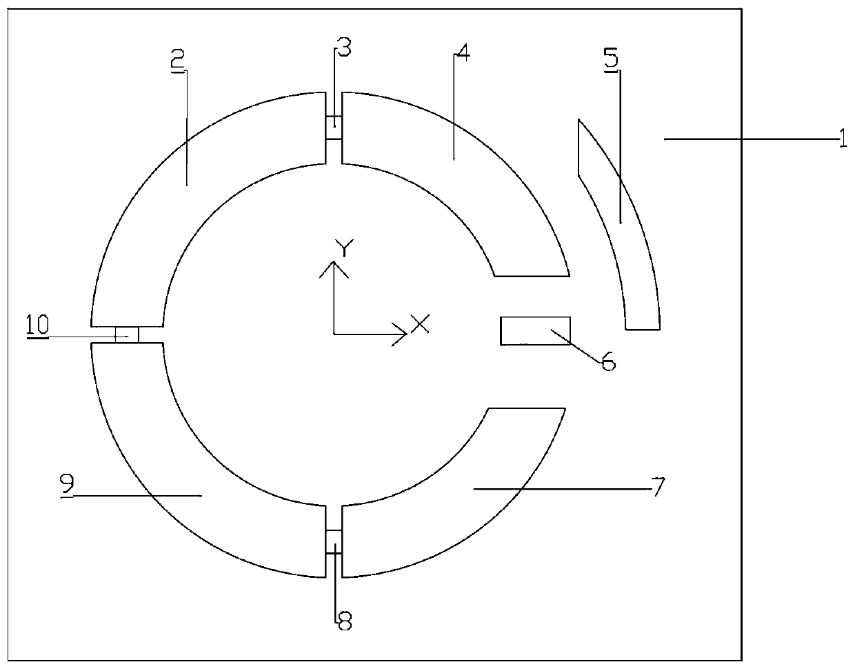
[0018] see figure 1 , the rectangular dielectric substrate 1 shown is a single-sided copper-clad high-performance microwave dielectric substrate with a dielectric constant of 2.2, a length of 90 mm, a width of 50 mm, and a thickness of 1 mm. The thickness of the copper clad film is 0.035mm.

[0019] Four ring patches are arranged on the surface of the copper-clad film of the rectangular dielectric substrate 1, which are respectively denoted as the first ring patch 2, the second ring patch 4, the third ring patch 7 and the fourth ring patch. Patch 9; the four ring patches are concentric circles and are separated from each other by grooves with a certain width; the outer ring radius of the ring patch is 29.8mm, and the inner ring radius is 21mm. Each ring patch The left and right sides of each are perpendicular to each other; between the first circular patch 2 and the second circular patch 4, between the first circular patch 2 and the fourth circular patch 9, between the third ...


PUM


Abstract

The invention discloses a circularly polarized loop microstrip antenna with a curving stub ground plane, belonging to the technical field of antennae. A copper coated film surface of a rectangular substrate is provided with four circular ring patches (2, 4, 7, 9) which are a concentric circle structure and are separated by a channel, wherein left and right sides of each circular ring patch are perpendicular to each other; three rectangular patches of the same size and one loading rectangular patch are orderly arranged in the channel, and the circular ring patches (2, 4, 7, 9) form antenna radiation elements; the circular ring patch (4) and the loading rectangular patch form a feed port; the copper coated film is also provided with a ring-shaped curving stub as an earth plate, and the earthplate and the circular ring patches are the concentric circle structure, and the left and right sides of the earth plate are perpendicular to each other; and a bottom edge in an axis-x direction is aligned with a central line of an axis-y direction of the loading rectangular patch. The antenna provided by the invention can easily realize conversion of left-handed and right-handed circularly polarized radiation waves, has relatively higher echo loss and wider impedance bandwidth, and has broadband circularly polarized characteristics.

Description

technical field [0001] The invention belongs to the technical field of antennas, in particular to a circularly polarized microstrip patch antenna used in satellite navigation, in particular to a circularly polarized circular microstrip antenna with a curved stub ground plane. Background technique [0002] Circularly polarized (CP) microstrip antenna (CPMA) has the advantage of low profile in the fields of satellite navigation, radio frequency identification (RFID) and mobile communication, and has been a research hotspot. In high-speed airborne communication, CPMA is a better choice for conformal design; in the use of satellite communication antennas, circularly polarized microstrip antennas can provide better versatility than linearly polarized antennas. In addition, because the excitation of the 90° phase difference bi-orthogonal mode is difficult to achieve circular polarization in a wide frequency range, the design of a wideband circularly polarized microstrip antenna wi...

Claims


Application Information

Patent Timeline
Patent Type & Authority Patents(China)
IPC IPC(8): H01Q1/38H01Q1/48H01Q9/04H01Q1/28
CPCH01Q1/288H01Q1/38H01Q1/48H01Q9/0428H01Q9/0464
Inventor 李德辉王宝续李伟文李秋浩
Owner JILIN UNIV
Learn More