Conjugate antenna structure oriented towards plasma coupling impedance rapid changes

A coupling impedance, plasma technology, applied in the direction of the connection of the antenna grounding switch structure, etc., can solve the problems of easy ignition and insufficient response time.

Active Publication Date: 2014-07-23
HEFEI CAS ION MEDICAL & TECHNICAL DEVICES CO LTD
View PDF2 Cites 9 Cited by
  • Summary
  • Abstract
  • Description
  • Claims
  • Application Information

AI Technical Summary

Problems solved by technology

Although it solves the problem that conventional short-circuit regulator adjusters are easy to spark, the response time of its adjustment is still far from enough compared to the change of ELM and the conversion of L-H mode
Moreover, if the existing superconducting tokamak and future reactors want to achieve their advanced and steady-state physical goals, the ion cyclotron system must be able to operate continuously and steadily, so a new deployment method must be developed to deal with the coupled The Matching Problem of Ion Cyclotronic System under the Condition of Rapid Impedance Variation

Method used


Image

  • Conjugate antenna structure oriented towards plasma coupling impedance rapid changes
  • Conjugate antenna structure oriented towards plasma coupling impedance rapid changes
  • Conjugate antenna structure oriented towards plasma coupling impedance rapid changes

Examples


Embodiment Construction

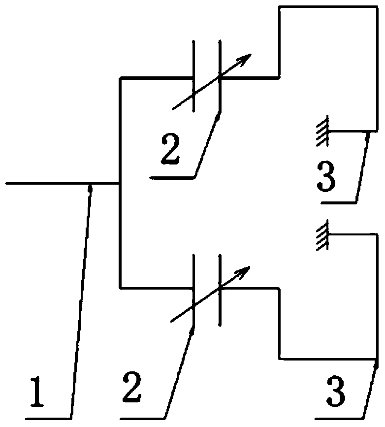
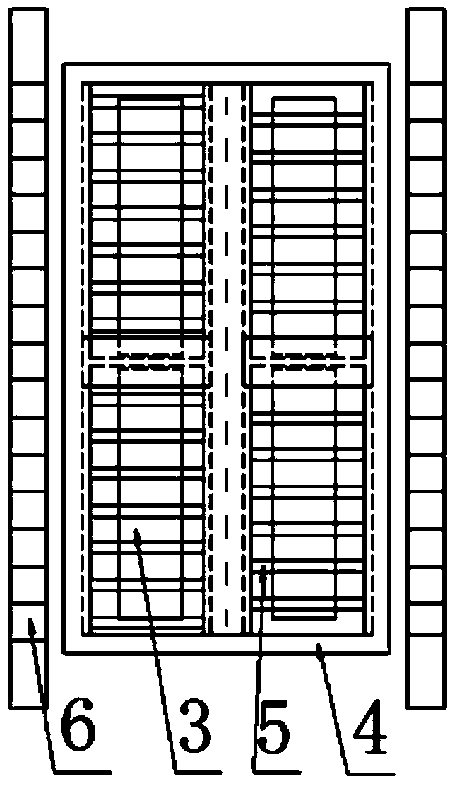
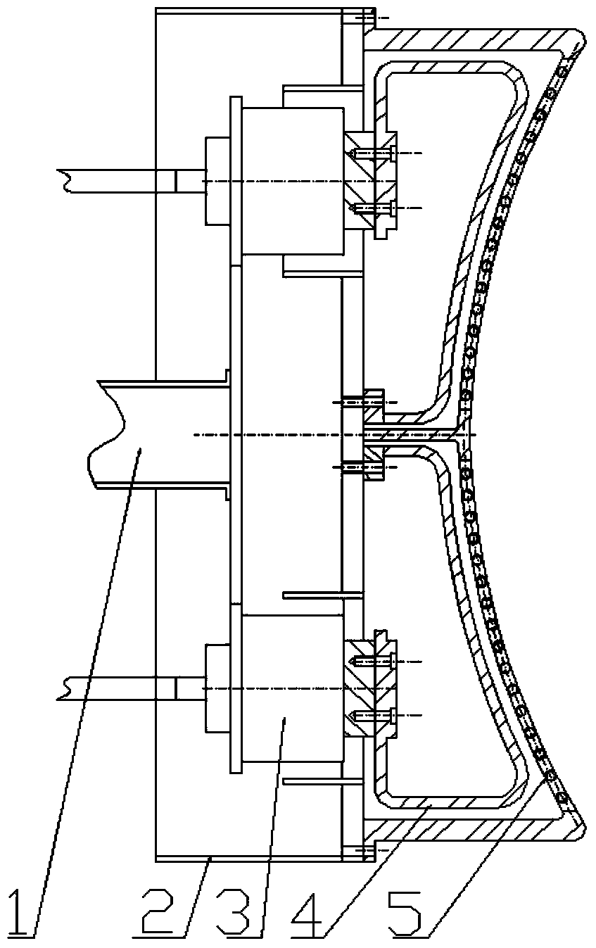
[0017] Such as Figure 1-3 As shown, a conjugate antenna structure facing rapid changes in plasma coupling impedance includes a box body 4, a Faraday shield 5 is fixed on the box body 4, and an antenna current strip 3 is arranged between the box body 4 and the Faraday shield 5, The antenna current strip 3 includes two polar current strips and two circular current strips. The feed-in ends of the two polar current strips are respectively connected to a matching capacitor 2, and the other ends of the two polar current strips are grounded. The matching capacitor 2 can be Adjust the vacuum capacitor, the adjustable vacuum capacitor is for a given characteristic impedance of the antenna, by adjusting the vacuum capacitor, the real part of the input impedance of the antenna at the feed point of the antenna is equal to the real part of the characteristic impedance of the vacuum transmission line, and its imaginary part The value is set to zero; two matching capacitors 2 are connected ...


PUM


Abstract

The invention discloses a conjugate antenna structure oriented towards plasma coupling impedance rapid changes. The conjugate antenna structure comprises a box, wherein a Faraday shield is fixed to the box, an antenna current strap is installed between the box and the Faraday shield, the antenna current strap comprises two polar current straps and two annular current straps, the feed-in ends of the two polar current straps are respectively connected with a matching capacitor, the other ends of the two polar current straps are grounded, adjustable vacuum capacitors serve as the matching capacitors, the two matching capacitors are connected through a T-shaped plate and a vacuum transmission line, and an impedance imaginary part on the central point of the T-shaped plate is zero; radio frequency power is fed into the two polar current straps through the same vacuum transmission line and through the matching capacitors respectively, so that a conjugate structure is formed; protection limiters are arranged on the two sides of the box respectively. According to the conjugate antenna structure oriented towards the plasma coupling impedance rapid changes, the whole system can be in a perfect matching state.

Description

technical field [0001] The invention relates to the field of radio frequency power coupling of an ion cyclotron wave heating system, in particular to a conjugate antenna structure facing rapid changes in plasma coupling impedance. [0002] Background technique [0003] The output impedance of the high-frequency transmitter in the ion cyclotron resonance heating system is 50 ohms, and the characteristic impedance of its transmission line is also 50 ohms, while the input impedance of the antenna is unknown, and it changes with the plasma and discharge parameters. Typically the real part of the antenna impedance varies between 0.5 and 10 ohms during discharge. This is clearly a mismatch compared to the characteristic impedance of the transmission line. In order to realize the matching between the transmission line impedance and the antenna impedance, it is necessary to introduce an adjustable matching device between the antenna and the high-frequency transmitter. In this way...

Claims


Application Information

Patent Timeline
Patent Type & Authority Applications(China)
IPC IPC(8): H01Q1/50
Inventor 袁帅赵燕平秦成明陈根程艳张新军王磊
Owner HEFEI CAS ION MEDICAL & TECHNICAL DEVICES CO LTD
Why Eureka
Try Eureka