Synchronous rectification implementation method

An implementation method and technology of synchronous rectification, which are applied in the direction of converting AC power input to DC power output, output power conversion devices, electrical components, etc., to achieve the effect of simple application

Active Publication Date: 2014-07-23
MORNSUN GUANGZHOU SCI & TECH
View PDF7 Cites 10 Cited by
  • Summary
  • Abstract
  • Description
  • Claims
  • Application Information

AI Technical Summary

Problems solved by technology

[0026] In view of this, the present invention solves the above-mentioned problems existing in the existing synchronous rectification circuit, and provides a method for implementing synchronous rectification, which does not require a large synchronous t

Method used


Image

  • Synchronous rectification implementation method
  • Synchronous rectification implementation method
  • Synchronous rectification implementation method

Examples


no. 1 example

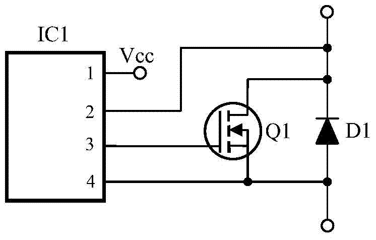
[0042] figure 1The schematic diagram of the first embodiment is shown. A synchronous rectifier tube Q1 is connected in parallel at both ends of the rectifier diode D1, which is applied to a synchronous rectification circuit device. It also includes an integrated circuit IC1. The integrated circuit IC1 adopts the technical solution in the content of the invention to control synchronization Rectifier tube Q1. The connection relationship is: the anode of the rectifier diode D1 is connected to the source S of the synchronous rectifier Q1, the cathode of the rectifier diode D1 is connected to the drain D of the synchronous rectifier Q1, Q1 is an N-channel MOS transistor, and the gate of the synchronous rectifier Q1 G is connected to the 3rd pin of the integrated circuit IC1, the 3rd pin of the integrated circuit IC1 is its driving pin, and the 1st pin of the integrated circuit IC1 is the power supply pin of IC1, which can be connected to the output voltage of the synchronous rectif...

no. 2 example

[0061] Figure 4 shows a second embodiment, Figure 4 The schematic diagram of the second embodiment is shown, in which a synchronous rectifier Q1 is connected in parallel at both ends of the rectifier diode D1, the difference from the first embodiment is that the synchronous rectifier Q1 is a P-channel MOS transistor. Applied to the synchronous rectification circuit device, it also includes an integrated circuit IC1, and the integrated circuit IC1 adopts the technical solution in the content of the invention to control the synchronous rectification tube Q1. The connection relationship is: the anode of the rectifier diode D1 is connected to the drain D of the synchronous rectifier Q1, the cathode of the rectifier diode D1 is connected to the source S of the synchronous rectifier Q1, Q1 is a P-channel MOS transistor, and the gate of the synchronous rectifier Q1 G is connected to the third pin of integrated circuit IC1, the third pin of integrated circuit IC1 is its driving pin...


PUM


Abstract

The invention discloses a synchronous rectification implementation method. The synchronous rectification implementation method includes: connecting a synchronous rectification tube with two ends of a rectification diode in parallel, detecting the forward conduction time t1 of the synchronous rectification tube and the rectification diode, subtracting a short time td from t1 to obtain a second time t2, using t2 to control the conduction of the synchronous rectification tube at least in the next cycle, as shown in the figure 17a, after stopping the synchronous rectification tube, enabling the rectification diode to finish the rectification for the section 17b, wherein the efficiency of the machine is rarely influenced. Through repeating the steps, a large synchronous transformer for isolation is omitted, and the application is simple; the synchronous rectification implementation method is suitable for different types of switching power supply topology, is capable of automatically adapting to the synchronous rectification under CCM and DCM, and is avoided from flowing backward.

Description

technical field [0001] The invention relates to the technical field of synchronous rectification, in particular to a method for realizing synchronous rectification. Background technique [0002] Both industrial and civil use often need to change the AC voltage of various grids into DC, and most of them are isolated DC. With the further requirements of national standards for the working efficiency of various electrical appliances, the current requirements for converters in electrical appliances ( Generally, switching power supply) requires higher and higher conversion efficiency. Other countries also attach great importance to it. For example, the U.S. Department of Energy has formulated many standards to regulate the efficiency of switching power supplies. Among them, the 80PLUS series of standards have high requirements for the efficiency of power supplies. Power supplies with gold medals and above must use synchronous rectifiers to meet the efficiency requirements. Requir...

Claims


Application Information

Patent Timeline
IPC IPC(8): H02M7/217
Inventor 王保均
Owner MORNSUN GUANGZHOU SCI & TECH
Why Eureka
Try Eureka