Passive optical fiber starring network with self-healing function

A technology of passive optical fiber and optical fiber sensor network, applied in the direction of optical fiber transmission, ring electromagnetic network, star electromagnetic network, etc., can solve the problems affecting the performance of sensor network, self-healing time limit, self-healing function interference, etc. Achieve the effect of good technology transformation foundation, good self-healing function, extensive social benefits and economic benefits

Active Publication Date: 2014-07-23
TIANJIN UNIV
View PDF4 Cites 7 Cited by
  • Summary
  • Abstract
  • Description
  • Claims
  • Application Information

AI Technical Summary

Problems solved by technology

This method can realize network self-healing, but in the implementation process, it is limited by the granularity of computer computing network, which makes the realization of self-healing function and the time of self-healing limited.
Patent No. 201010252698.8 "A Large-Capacity Self-healing Optical Fiber Sensor Network" also mentions a large-capacity self-healing optical sensor network, which uses active device optical switches to achieve network self-healing. In certain occasions (such as in a strong electric field), the self-healing function of the network will be disturbed by the external environment, which will affect the performance of the sensor network
It can be seen that the current research on the self-healing of optical fiber sensor networks is mainly realized by using active devices, and there is no optical fiber sensor network with self-healing functions based on passive devices.

Method used


Image

  • Passive optical fiber starring network with self-healing function
  • Passive optical fiber starring network with self-healing function

Examples


Embodiment Construction

[0018] The embodiments of the present invention will be further described in detail below in conjunction with the accompanying drawings.

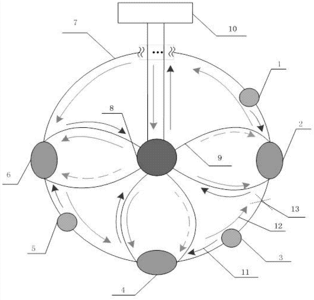
[0019] like figure 1 As shown, the star ring network contains N sensors (1, 2...N), all the sensors are distributed on the ring network, and the sensors rely on connecting optical fiber 7 and 1×2 coupler 1, 1×2 coupler 2 , ... The input branch 2 and the output branch 3 of the 1×2 coupler N are connected to form a ring network. One end of the star network is the output end of the 2×N coupler 8 , and the other end is composed of N input-end branches 1 of the 1×2 couplers. No sensors are arranged on the star network. The upper ring network of the entire star ring network has N connecting optical fibers, and the lower ring network has 2N connecting optical fibers. When the light source in the central node 10 emits a beam of optical signals, after passing through the 2×N coupler 8, the beam is divided into N optical signals, and transmitted t...


PUM


Abstract

The invention discloses a passive optical fiber starring network with a self-healing function. The passive optical fiber starring network comprises a starring network serving as the upper layer network and an annular network serving as the lower network, and further comprises a central node provided with a light source. An incident light signal sent by the light source is divided into N paths of optical signals through a 2*N coupler arranged on the central node, the N paths of optical signals are sent to N 1*2 couplers connected with the 2*N coupler, and therefore the starring network is formed. All branches of all the 1*2 couplers are connected in an adjacent mode and provided with FBG sensors, and therefore the annular network is formed. In each FBG sensor of the annular network, when an optical fiber of one branch is broken, the upstream optical signals on the other branches can still be transmitted to the FBG sensor, sensing signal emission exists all the time, all the FBG sensors on the annular network are kept in the normal working state, and therefore the self-healing function is achieved. According to the passive optical fiber starring network, self-healing of the sensor network can be achieved in the severe electromagnetic interference environment, and the passive optical fiber starring network has wide social benefits and economic benefits.

Description

technical field [0001] The patent of this invention relates to a passive optical fiber sensor network with self-healing ability, which is one of the technologies of the Internet of Things. Background technique [0002] The emergence of Internet of Things technology has brought a new revolution to the development of information technology. The Internet of Things is an information interaction between things and things, people and things, and is an extension of the sensor network. The sensor network is a network composed of sensor nodes, which is the basis for realizing the Internet of Things. At present, there are mainly two modes of sensor networks, one is optical fiber sensor network and the other is wireless sensor network. , can only be used alone. With the increase of the number of sensor nodes in the sensor network, the reliability of the sensor network is particularly important. In particular, the breakage of the connecting optical fiber will cause a large number of...

Claims


Application Information

Patent Timeline
Patent Type & Authority Applications(China)
IPC IPC(8): H04B10/272H04B10/275H04B10/075H04B10/25
Inventor 贾大功张玉龙张红霞刘铁根张以谟
Owner TIANJIN UNIV
Why Eureka
Try Eureka