
Manufacturing device for tire ply material

A tire cord and layer material technology, applied in tires, applications, household appliances, etc., can solve the problems of poor versatility, difficult to use transfer devices effectively, etc.

Active Publication Date: 2016-10-05
SUMITOMO RUBBER IND LTD
View PDF4 Cites 0 Cited by
  • Summary
  • Abstract
  • Description
  • Claims
  • Application Information

AI Technical Summary

Problems solved by technology

Therefore, when the tire cord is a non-magnetic body such as an organic fiber cord, or when the cutting member 13 has a large area and a large mass, it is difficult to effectively use the transfer device (c)
In addition, when the angle θ of the cutting member 13 is changed, the configuration angle α of the conveyor (d) needs to be changed, thus resulting in poor versatility

Method used


Image

  • Manufacturing device for tire ply material
  • Manufacturing device for tire ply material
  • Manufacturing device for tire ply material

Examples


Embodiment Construction

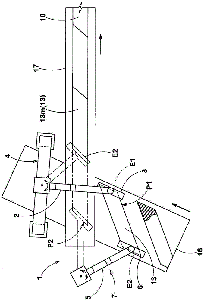
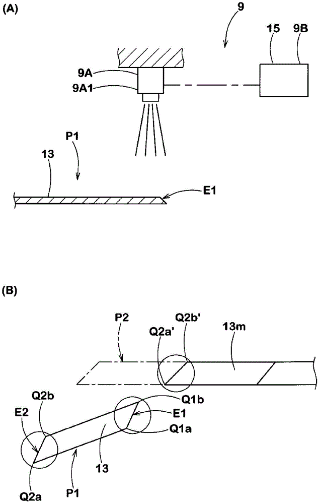
[0037] Embodiments of the present invention will be described more specifically with reference to the accompanying drawings. Such as figure 1As shown in , the manufacturing equipment for tire carcass material of the present embodiment (hereinafter sometimes simply referred to as "carcass material manufacturing equipment") 1 makes the cutting member 13-the cutting member 13 has been moved by such as a belt conveyor The conveying device 16 is placed at the loading position P1 - moves to the joining position P2 on the conveyor 17 and then joins the cut piece 13 to another cut piece 13m previously placed at the joining position P2 to form a longer tire Ply material 10.

[0038] Such as Figure 11 As shown in , the cutting member 13 has a parallelogram shape obtained by sequentially cutting longer strip-shaped bodies 12 at an angle θ with respect to the cord longitudinal direction of the tire cord 11, in which, The aligned bodies of a plurality of parallel tire cords 11 are cove...


PUM


Abstract

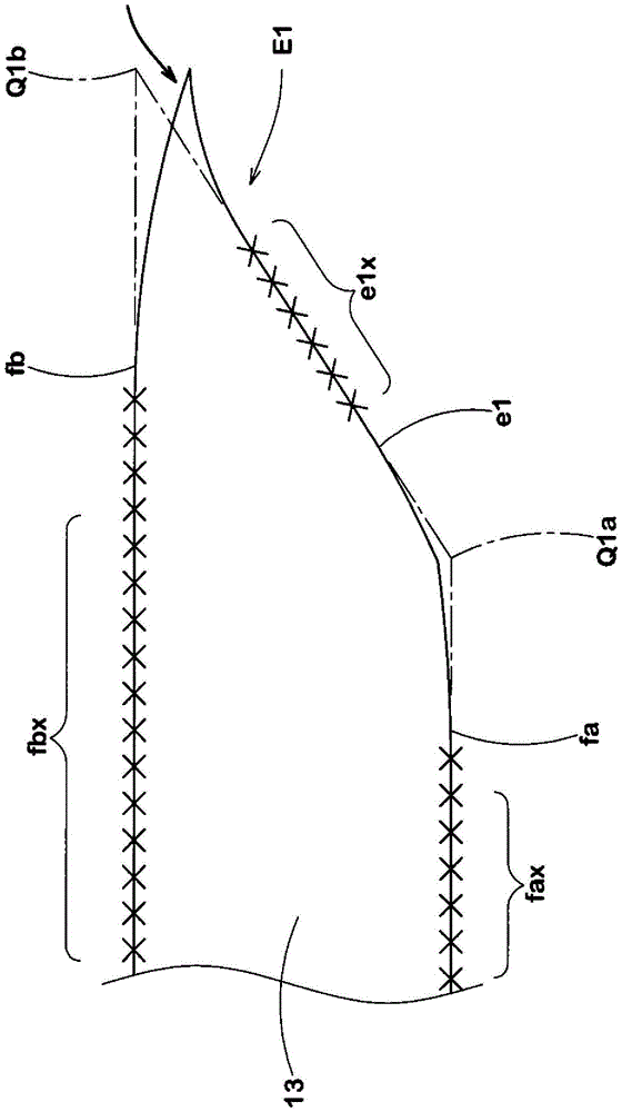
The device for manufacturing tire ply material efficiently and with high precision is equipped with: a first gripping-moving device provided with a first gripping tool, which grips the first connection edge of a cut piece at the emplacement position, on the tip of a first robot arm; and a second gripping-moving device provided with a second gripping tool, which grips the second connection edge, on the tip of a second robot arm. The first gripping tool comprises a gripping means on one side that grips the end portion on one side of the first connection edge of the cut piece and a gripping means on the other side that grips the end portion on the other side of the cut piece, and is provided with a stretching means that draws the gripping means away from each other to stretch the cut piece gripped therewith.

Description

technical field [0001] The present invention relates to manufacturing equipment for tire ply material which sequentially joins cut pieces to each other at joining positions, for example on a conveyor, thereby ensuring high precision and efficient production of materials usable for carcass ply, belt Or tire ply material in the like. Background technique [0002] Such as Figure 11 Conceptually shown in FIG. 1 , a tire ply material 10 for use, for example, in a carcass ply and a belt is formed of a long strip 12 . In the strip 12, parallel aligned tire cords 11 are covered with unvulcanized rubber. The parallelogram cut piece 13 is formed by sequentially cutting the strip-like body 12 at a predetermined angle θ with respect to the longitudinal direction of the tire cord 11 . When the tire ply material 10 is a carcass ply, the angle θ is generally about 90 degrees, and when the tire ply material 10 is a belt, the angle θ is generally between 10 degrees and 40 degrees. The op...

Claims


Application Information

Patent Timeline
Patent Type & Authority Patents(China)
IPC IPC(8): B29D30/38
CPCB29D30/42B29D2030/421B29D2030/4406
Inventor 兼松尚兴
Owner SUMITOMO RUBBER IND LTD
Learn More