Supercharge Your Innovation With Domain-Expert AI Agents!

A compensator

A technology of compensator and motion compensation, which is applied in the direction of drilling equipment, earthwork drilling, drill pipe, etc., and can solve the problems of being easily affected by mechanical failure and loss of drill string compensation

Active Publication Date: 2014-07-23
AKER MH
View PDF7 Cites 1 Cited by
  • Summary
  • Abstract
  • Description
  • Claims
  • Application Information

AI Technical Summary

Problems solved by technology

Active compensating winches are also susceptible to mechanical failures resulting in complete loss of drill string compensation

Method used


Image

  • A compensator
  • A compensator

Examples


Embodiment Construction

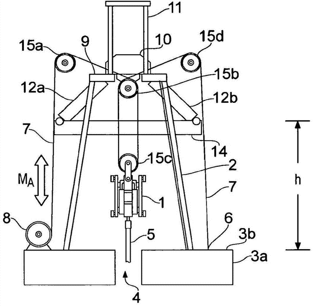
[0021] figure 1 is a schematic diagram of a motion compensator system in active mode according to the present invention. The crane 2 is supported by a floating vessel (schematically indicated at 3a) with a deck structure 3b. The drilling rig 1 is suspended by a crane and controls a drill string 5 which extends through the moonpool 4, into the water and to the seabed (not shown). Such arrangements are well known in the art.

[0022] The drill string 5 is suspended by the fixed pulley 10 via the drilling machine 1 and the cable-and-pulley arrangement 7, 15b, 15c. In this active compensation mode, the fixed sheave 10 rests on (and preferably is threaded to) the water table 9 in the crane. A drawworks 8 is connected to the deck structure 3b and to the drilling rig 1 via a cable 7 extending through the pulleys 15a to 15d and to a connection point 6 on the deck structure (the required energy supply and control equipment have been omitted in the figure , hydraulic hoses, etc., as...


PUM


Abstract

A motion compensation system for controlling relative movements between a floating vessel (3a) and an elongate element (5), where the elongate element is suspended by the vessel at a first end and extends into a body of water below the floating vessel. An active motion compensator (8) is connected to the elongate element first end via an element (10) arranged in an upper region of an erect support structure (2) and a passive motion compensator (12a,b) is connected to the elongate element first end via the element (10). The motion compensators (8, 12a,b) are structurally and operationally separate and independent units and are configured for separate and mutually independent operation.

Description

technical field [0001] The present invention relates to oil and gas drilling with floating structures, and related operations. More specifically, the invention relates to a motion compensation system as stated in the preamble of claim 1 . Background technique [0002] Floating vessels (ships, platforms, etc.) are commonly used for drilling, servicing and maintenance of subsea oil and gas wells. Typically, a riser is suspended below the drill floor and extends to a subsea wellhead on the seabed. A drill string may be suspended by a drilling derrick (drilling derrick) and extend in a riser through the wellhead and into a subterranean hydrocarbon reservoir. The distance between the seabed wellhead and the reservoir (and thus the resulting drill string length) can be considerable. In this configuration, the riser is fixed to the seabed (via the wellhead), while the drill string is not fixed. Because the drill string runs in the riser, a failed drill string or drill string co...

Claims


Application Information

Patent Timeline
Patent Type & Authority Applications(China)
IPC IPC(8): E21B19/09
CPCE21B19/09E21B19/004E21B19/006
Inventor 拉尔斯·波赫纳
Owner AKER MH
Features
  • R&D
  • Intellectual Property
  • Life Sciences
  • Materials
  • Tech Scout
  • Unparalleled Data Quality
  • Higher Quality Content
  • 60% Fewer Hallucinations
Learn More