Reciprocating Engines and Engine Blocks

An engine, reciprocating technology, applied in the direction of engine components, combustion engines, machines/engines, etc., can solve problems that hinder turbocharger operation, engine operation, cylinder filling effects, etc.

Active Publication Date: 2016-03-30
WARTSILA FINLAND OY
View PDF5 Cites 0 Cited by
  • Summary
  • Abstract
  • Description
  • Claims
  • Application Information

AI Technical Summary

Problems solved by technology

For example, in a turbocharged reciprocating engine, intake pressure pulsations can repeatedly move the operating point of the turbocharger into the surge region, which hinders the operation of the turbocharger and thus is detrimental to the operation of the engine Impact
Furthermore, pressure pulsations in the inlet channel also have an adverse effect on the filling of the cylinder

Method used


Image

  • Reciprocating Engines and Engine Blocks
  • Reciprocating Engines and Engine Blocks

Examples


Embodiment Construction

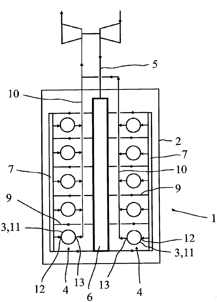
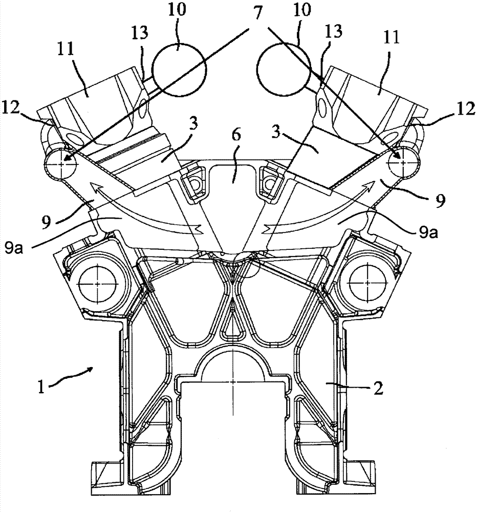
[0012] figure 1 A multi-cylinder reciprocating engine 1 is disclosed. The engine 1 can be a large reciprocating engine, a two-stroke or four-stroke engine. Here, a large reciprocating engine is referred to as an engine that can be used, for example, as a main engine and a secondary engine in a ship or in a power plant for generating heat and / or electricity. The engine 1 comprises an engine block 2 with cylinders 3 arranged in two banks 4 in a V-shaped configuration. Typically, engine 1 includes 6 to 24 cylinders 3 .

[0013] The reciprocating engine 1 comprises inlet channels 5 for guiding intake air into the cylinders 3 . The engine 1 can adopt one-stage or multi-stage turbocharging 8 . exist figure 1 In the embodiment described above, the engine is one-stage turbocharged and provided with one turbocharger 8, however, each cylinder bank 4 may be provided with a separate turbocharger 8 if desired. The inlet channel 5 is provided with a main air intake receiver 6 and two ...


PUM


Abstract

A reciprocating engine (1) comprising an engine block (2) with cylinders (3) and inlet passages (5) for guiding intake air into the cylinders (3). The inlet passage (5) is provided with a main intake receiver (6) and at least one auxiliary intake receiver (7), and the auxiliary intake receiver (7) is arranged on the main intake receiver (6) ) and upstream of the cylinder (3).

Description

technical field [0001] The invention relates to a reciprocating engine comprising an engine block having cylinders and inlet passages for directing intake air into the cylinders. The invention also relates to an engine block of a reciprocating engine. Background technique [0002] It is known to generate intake pressure pulsations in the inlet passage of a reciprocating engine. For example, in a turbocharged reciprocating engine, intake pressure pulsations can repeatedly move the operating point of the turbocharger into the surge region, which hinders the operation of the turbocharger and thus is detrimental to the operation of the engine Impact. Furthermore, pressure pulsations in the inlet channel also have an adverse effect on the filling of the cylinder. This is because the pressure level fluctuates in the vicinity of each inlet valve, and when the inlet valve is closed, the amount of air retained in the cylinder is determined by the local pressure level. Partial pre...

Claims


Application Information

Patent Timeline
IPC IPC(8): F02M35/10F02F1/42F02M35/104F02M35/116
CPCF02M35/10288F02M35/116F02M35/165F02F7/0012F02M35/10026F02B29/02F02B33/44F02M35/10045
Inventor 阿尔托·耶尔维D·哈格布卢姆
Owner WARTSILA FINLAND OY
Why Eureka
Try Eureka