

Manipulator clamp and robot with manipulator clamp
A technology of manipulators and fixtures, applied in the direction of manipulators, chucks, manufacturing tools, etc., can solve problems that affect work efficiency, low precision, and workpiece damage, and achieve the effects of improving work efficiency, high precision, and efficient positioning and handling
- Summary
- Abstract
- Description
- Claims
- Application Information
AI Technical Summary
Problems solved by technology
Method used
Image

Examples
Embodiment 1
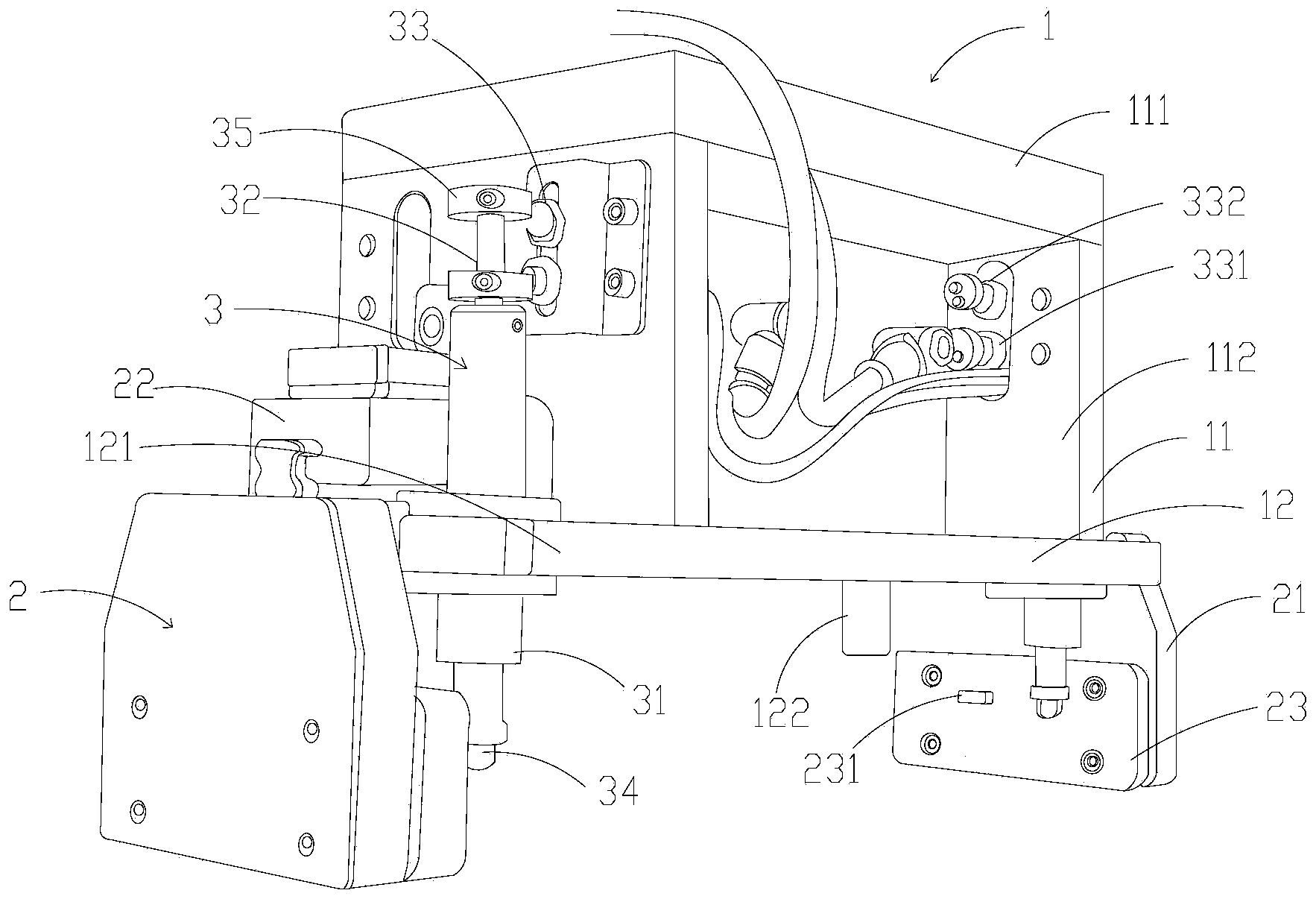
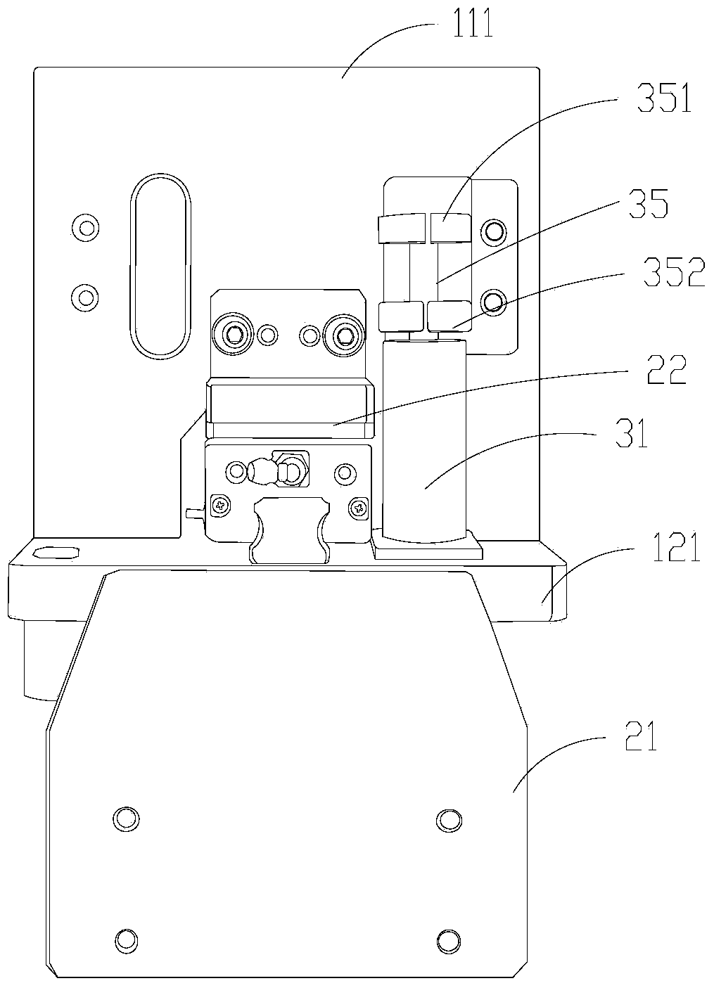
[0025] Such as figure 1 , figure 2 As shown, a manipulator clamp includes a top frame 1, a clamping mechanism 2 and a lower pressure position sensing device 3, the clamping mechanism 2 is slidably installed on the bottom end of the top frame 1, and the lower pressure position sensing device 3 is installed on the top frame 1 to detect the relative position of the clamped workpiece after the clamping mechanism 2 is pressed down, and triggers the clamping mechanism 2 to act.
[0026] The top frame 1 is used for carrying and installing the clamping mechanism 2, the downward pressure position sensing device 3 and other components. The top frame 1 includes a bottom plate 12 and a frame body 11 disposed on the bottom plate 12 . The frame body 11 includes a top wall 111 and two side walls 112 supporting the top wall 111 , a control system or other necessary components can be accommodated between the side walls 112 , such as a connecting body for connecting with the main shaft at th...
Embodiment 2
[0036] Such as Figure 4 As shown, a manipulator clamp includes a top frame (not fully shown, only the top wall 111 is shown), a connecting body 101, a flange assembly 102, a clamping mechanism 2 and a lower pressure position sensing device 3, the clamping The mechanism 2 is slidably installed on the bottom end of the top frame, and the lower pressure sensing device 3 is used to detect that the clamping mechanism 2 presses against the position of the workpiece to be clamped, so as to trigger the signal to make the clamping mechanism 2 perform the clamping action .
[0037] The top frame is the structure shown in Embodiment 1, including a bottom plate (not shown in the figure) and a frame set on the bottom plate. The frame body includes a top wall 111 and two side walls (not shown) supporting the top wall 111 . The connecting body 101 is used to connect with the main shaft at the end of the robot arm, and it is accommodated between the side walls. The flange assembly 102 is ...
Embodiment 3
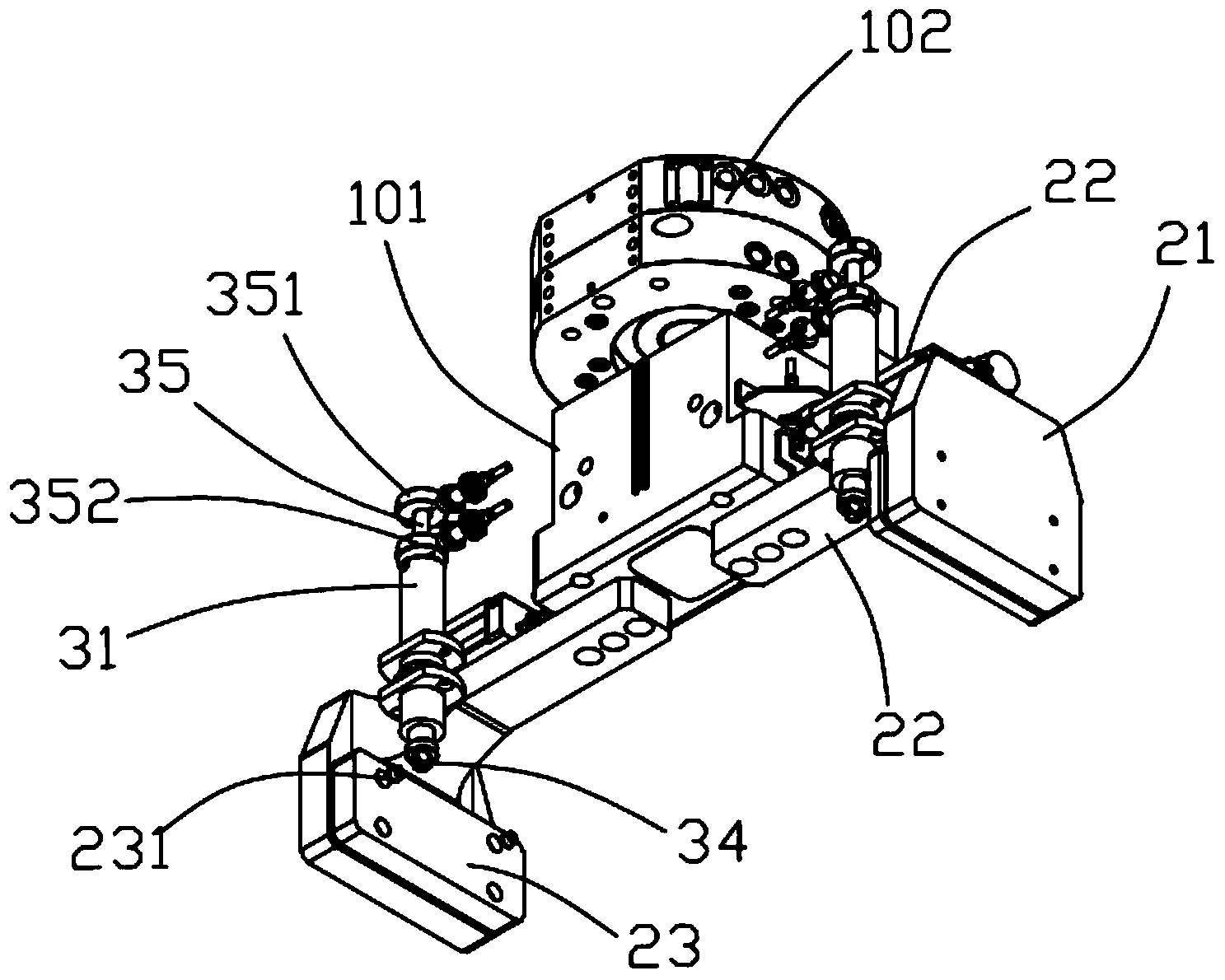
[0043] see Figure 5 , Figure 6 , a manipulator clamp, including a top frame, a connecting body 101, a flange assembly 102, a clamping mechanism 2 and a lower pressure position sensing device 3, the clamping mechanism 2 is slidably installed at the bottom of the top frame 1, the The lower pressure position sensing device 3 is used to detect the position where the clamping mechanism 2 presses against the workpiece to be clamped, and triggers the signal to make the clamping mechanism 2 perform a clamping action.
[0044] The top frame is the structure shown in Embodiment 1, including a bottom plate 12 and a frame body 11 arranged on the bottom plate 12 . The frame body includes a top wall 111 and two side walls 112 supporting the top wall 111 . The connecting body 102 is used to connect with the main shaft of the end of the robot arm, which is fixed on the top wall 111 and accommodated between the side walls 112 . The flange assembly 102 is arranged on the top wall 111 and i...
PUM
 Abstract
Description
Claims
Application Information