
Energy saving control method of pneumatic ash conveying system in thermal power plant

A technology of pneumatic ash conveying and control methods, which is applied in the direction of conveyors, transportation and packaging, and conveying bulk materials, etc. It can solve the problems of large fluctuations in compressed air volume, frequent start and stop of air compressors, and unbalanced energy consumption. Achieve the effect of reducing quantity, reducing pressure wave drop and reducing energy consumption

Active Publication Date: 2016-05-25
内蒙古电力勘测设计院有限责任公司
View PDF5 Cites 0 Cited by
  • Summary
  • Abstract
  • Description
  • Claims
  • Application Information

AI Technical Summary

Problems solved by technology

[0002] The output of the pneumatic conveying system in a thermal power plant is often required to leave a large amount in the design. The design output is generally 120-200% of the total ash discharge of the coal used. In the case of no change, 20-50% of the system is doing useless work, especially when the boiler unit is operating at low load, the probability of empty operation of the pneumatic conveying system is greater, and some stages of its operation are dilute-phase conveying. This design In principle, for large and medium-sized units and power plants with a large number of units, the probability of running and stopping multiple ash conveying pipelines at the same time will increase, so the amount of compressed air required for transportation will fluctuate greatly. The air compressor starts and stops frequently, the energy consumption is unbalanced, and the power consumption is large

Method used


Image

  • Energy saving control method of pneumatic ash conveying system in thermal power plant
  • Energy saving control method of pneumatic ash conveying system in thermal power plant
  • Energy saving control method of pneumatic ash conveying system in thermal power plant

Examples


Embodiment Construction

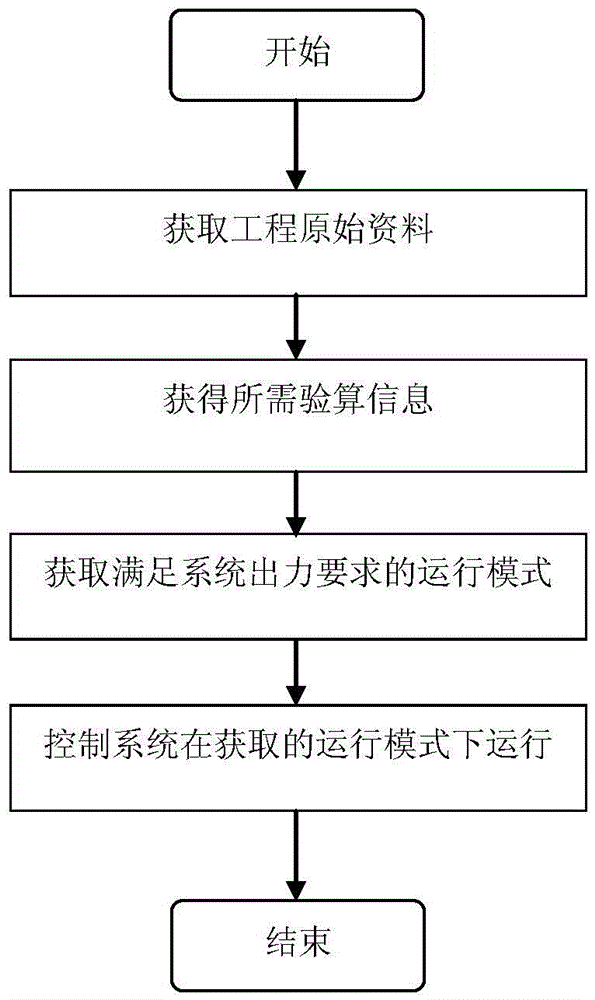
[0020] See figure 1 The main steps of the method proposed by the present invention include: obtaining the original engineering data, obtaining the information required for the verification calculation based on the original data, obtaining the operating mode that meets the system output requirements based on the information required for the verification calculation, and placing the system in the obtained operating mode run. These steps are described in further detail below.

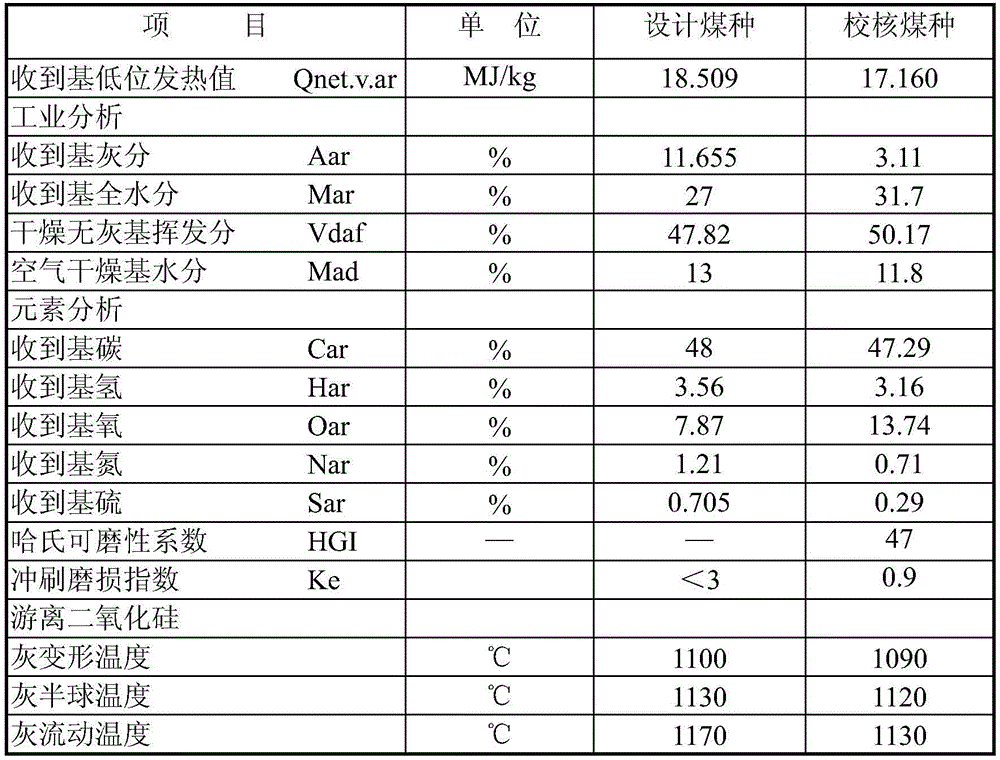
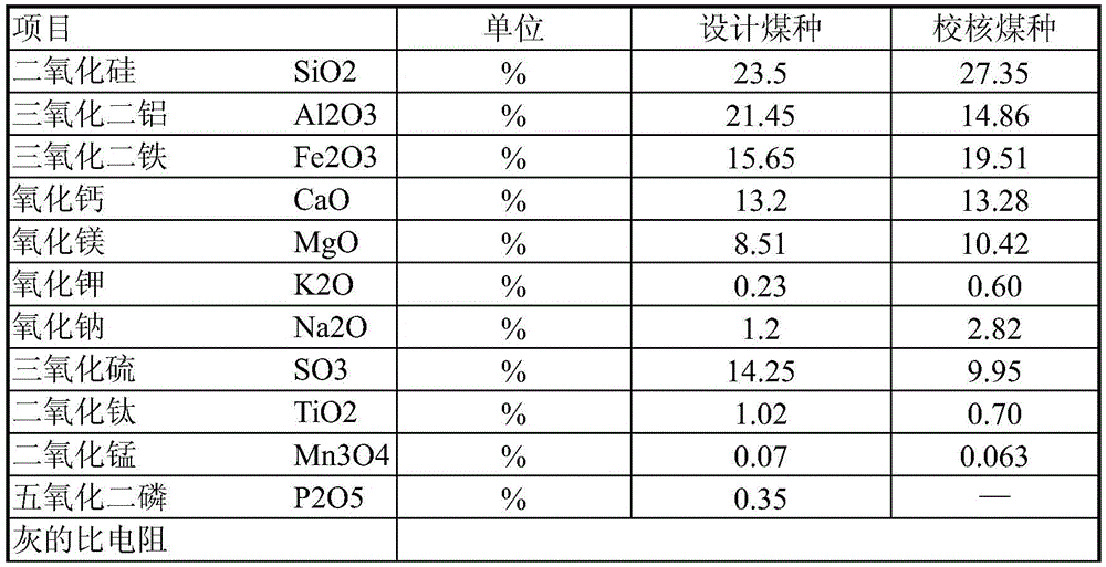
[0021] Obtain the original engineering materials of thermal power plants. The original data of the project include unit capacity, quantity, design and check coal quality data, the number and volume of dust hoppers, and the ash conveying system configuration of each dust collection area. The ash conveying system configuration of each dust collection area includes the ash discharge volume, the number and volume of silo pumps, the number and specifications of ash conveying pipelines, and the conveying length. ...


PUM


Abstract

An energy-saving control method for the pneumatic ash conveying system of a thermal power plant is proposed, which belongs to the technical field of thermal power plant control. The mode of operation required by the system effort, and placing the system in the resulting mode of operation. The method can reduce the number of simultaneous operation of each conveying pipeline of the unit to reduce the energy consumption of the operation, and can take into account the safety of the system, thereby improving the flexibility and robustness of the control.

Description

Technical field [0001] The invention relates to the technical field of thermal power plant control, in particular to an energy-saving control method of a pneumatic ash conveying system in a thermal power plant. Background technique [0002] The output of the pneumatic conveying system of thermal power plants is often required to be designed with greater desire. Its design output is generally 120 to 200% of the total ash discharge of the coal-fired type. In this way, even if the boiler unit is operating at full load, if the coal Under the condition of no change, 20-50% of the system is doing wasteful work. Especially when the boiler unit is operating at low load, the probability of idling operation of the pneumatic conveying system is greater. Part of the operation is dilute phase conveying. This design Principles For large and medium-sized units and power plants with a large number of units, the chances of multiple ash conveying pipelines running and stopping at the same time wil...

Claims


Application Information

Patent Timeline
Patent Type & Authority Patents(China)
IPC IPC(8): B65G53/66
Inventor 金维勤潘仁湖范雄辉薛红艳
Owner 内蒙古电力勘测设计院有限责任公司
Learn More