
Balance disc used in solid-liquid two-phase flow conveying

A technology of balance disk and phase flow, which is applied to the components of pumping devices for elastic fluids, liquid fuel engines, non-variable pumps, etc. Set vibration and noise and other problems to achieve the effect of reducing cavitation damage, prolonging service life and reducing mechanical wear

Active Publication Date: 2014-07-30
ZHEJIANG SCI-TECH UNIV
View PDF6 Cites 2 Cited by
  • Summary
  • Abstract
  • Description
  • Claims
  • Application Information

AI Technical Summary

Problems solved by technology

For high-speed pumps, especially in solid-liquid two-phase flow, when solid particles such as sediment in the medium enter the balance disc, it will also accelerate the wear of the balance disc, especially at the edge of the balance disc due to high speed and easy The wear caused by contact seriously affects the stable operation life of the pump; 2. The impact of cavitation near the balance plate: due to the high impact frequency when cavitation occurs, it will cause plastic deformation and local hardening, and metal fatigue. Until the metal surface forms honeycomb holes and other mechanical denudation, these will accelerate the destruction of the balance disc
[0004] When the balance plate is worn too much, it must be replaced, otherwise it will cause the radial unbalance of the shaft to increase, causing the vibration and noise of the pump unit, and in severe cases, the pump shaft may be damaged. When replacing the balance plate, the pump needs to be returned to the factory for disassembly , Replacing parts and reinstalling, the transportation cycle is long, which will inevitably affect production efficiency

Method used


Image

  • Balance disc used in solid-liquid two-phase flow conveying
  • Balance disc used in solid-liquid two-phase flow conveying
  • Balance disc used in solid-liquid two-phase flow conveying

Examples


Embodiment Construction

[0024] The present invention will be further described below in conjunction with drawings and embodiments.

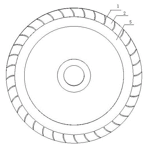
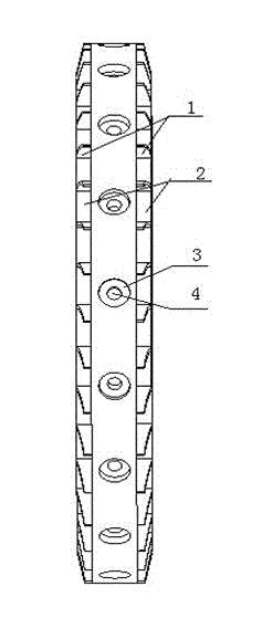
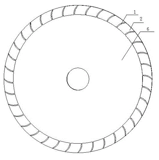
[0025] like figure 1 , image 3 As shown, the peripheral surfaces on both sides of the balance disk are the working surface and the non-working surface respectively, one side of the working surface of the balance disk is provided with an annular convex surface 5, and the edges of the peripheral surfaces on both sides of the balance disk are provided with blades 1 evenly spaced along the circumference, The blades 1 on both sides are located on the same plane as the circumferential surfaces on both sides, and there is a notch between two adjacent blades 1, such as figure 2 , Figure 4 As shown, blind holes are evenly distributed on the side of the cylinder of the balance plate, and the blind holes on both sides symmetrically in the center of the balance plate are equipped with bolts 7 for adjusting the counterweight of the balance plate, and spring plates 8 are install...


PUM


Abstract

The invention discloses a balance disc used in solid-liquid two-phase flow conveying. Blades uniformly distributed along the circumference at intervals are arranged at the edges of the circumferential surfaces at two sides of the balance disc; a notch slot is formed between each two adjacent blades; each blade is of a cylindrical rear bent blade; blind holes are uniformly distributed in the cylindrical side surface of the balance disc at intervals; bolts for adjusting balance disc counter weights are arranged in the blind holes in two sides in central symmetry; leaf springs and gaskets for finely tuning the counter weights are arranged between the bolts and the blind holes. The mechanical abrasion and the cavitation damage to the balance disc can be effectively reduced, the noise in the operation of a pump is reduced, and the service life is prolonged; when the balance disc is subjected to the dynamic balance adjustment, the balance quantity of the balance disc can be more conveniently adjusted under the condition that the counter weights on the surface of the disc body are not polished or spot-welded, and the vibration, noise and radial unbalance force which are generated in the motion process of the pump are reduced; the needs of pumps in the fields such as petroleum, chemical industry and water conservancy can be met.

Description

technical field [0001] The invention relates to a balance disc, in particular to a balance disc used in solid-liquid two-phase flow conveyance. Background technique [0002] The balance device is generally common in centrifugal pumps, and it generally includes a balance disc and a balance drum. The balance disc and the balance drum are installed behind the final stage impeller and rotate together with the rotor. The balance disc is used to balance the axial force. The working principle of the balance disc is as follows: the liquid with pressure from the final stage flows into the cavity in front of the balance disc through the radial gap of the adjustment sleeve, and the cavity is in a high-pressure state. There is a balance tube connected to the pump inlet behind the balance plate, and its pressure is approximately the inlet pressure. In this way, the pressure on both sides of the balance plate is unequal, thus generating a backward axial thrust, that is, a balance force...

Claims


Application Information

Patent Timeline
Patent Type & Authority Applications(China)
IPC IPC(8): F04D29/041
Inventor 崔宝玲饶昆方晨张鑫
Owner ZHEJIANG SCI-TECH UNIV
Learn More