Electromagnetic drive positioning control method and application of the same

A positioning control and electromagnetic technology, applied in the direction of adaptive control, general control system, control/adjustment system, etc., can solve the problems of precise drive control of difficult-to-drive systems

Active Publication Date: 2014-07-30
SHANGHAI JIAO TONG UNIV
View PDF2 Cites 9 Cited by
  • Summary
  • Abstract
  • Description
  • Claims
  • Application Information

AI Technical Summary

Problems solved by technology

However, since this method is a model (transfer function model) constructed by the inherent physics of the controlled object or given structural or system characteristics, it is not suitable for unsteady environments and time-varying controlled objects/systems, that is, using offline Obv

Method used


Image

  • Electromagnetic drive positioning control method and application of the same
  • Electromagnetic drive positioning control method and application of the same
  • Electromagnetic drive positioning control method and application of the same

Examples


Embodiment 1

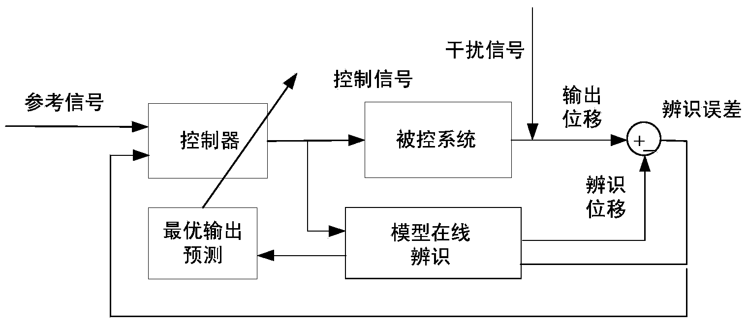
[0069] In the following, GMA (giant magnetostrictive actuators, giant magnetostrictive actuators) as the controlled system will be described in detail.

[0070] Such as figure 1 As shown, the present embodiment provides an electromagnetically actuated positioning control method for realizing precise driving and high-precision vibration control of giant magnetostrictive actuators (giant magnetostrictive actuators, GMA). Accurate identification and description, and linear compensation control can be performed on it to ensure the effectiveness of precise driving and vibration control.

[0071] Such as figure 1 As shown, the electromagnetic actuation drive positioning control method provided in this embodiment includes an adaptive feedback control process, specifically including the following steps:

[0072] Step 1.1, model online identification: establish the controlled autoregressive moving average model (CARMA) of the controlled system, and realize the The model is built and...

Embodiment 2

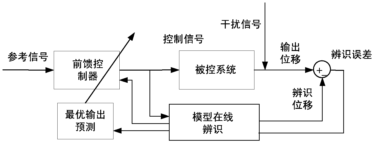
[0100] Such as figure 2 As shown, the electromagnetic actuation drive positioning control method provided in this embodiment includes an adaptive feedforward control process, which specifically includes the following steps:

[0101] Step 2.1, establishing a feedforward control model of the controlled system;

[0102] In step 2.2, the control current of the controlled system is assigned to the feed-forward control model, and the actual output displacement of the controlled system is obtained to realize a cyclic open-loop control.

[0103] In this embodiment, the feedforward control model is established in the following way:

[0104] -Establish the controlled autoregressive sliding average model of the controlled system, and realize the online construction and identification of the model for the controlled system through the combination of the controlled autoregressive sliding average model and the recursive augmented least square method, forming an identification feedforward ...

Embodiment 3

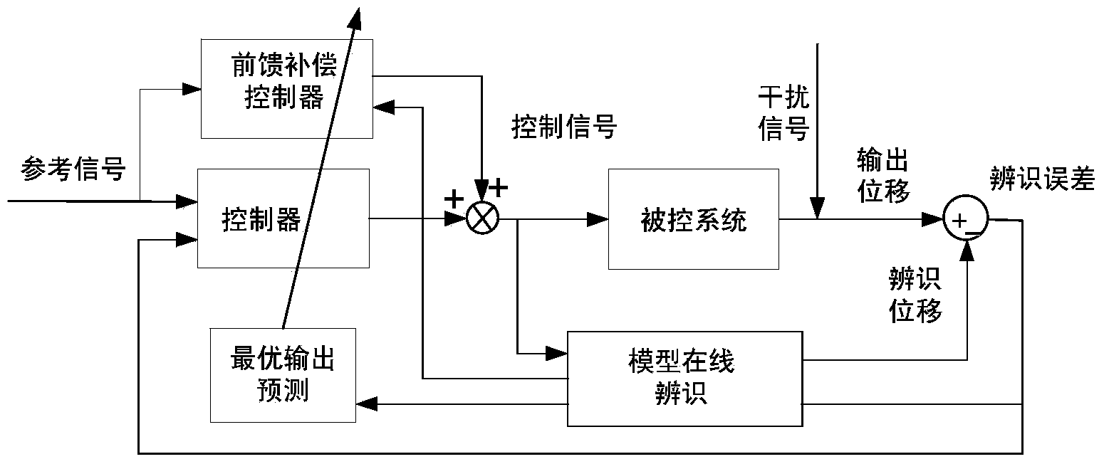
[0108] Example 3 is a combination of Examples 1 and 2.

[0109] Such as image 3 As shown, the electromagnetic actuation drive positioning control method provided in this embodiment includes the adaptive feedback control process provided in Embodiment 1 and the adaptive feedforward control process provided in Embodiment 2. The combination of the two processes realizes the precise positioning control of GMA .

[0110] From image 3 It can be seen from the figure that this embodiment combines the two algorithms of the feedback control process and the feedforward control process, which not only retains the high control accuracy and efficiency of the feedback control process of Embodiment 1, but also has the good timeliness of the feedforward control process of Embodiment 2 , while introducing a feed-forward link to effectively compensate the closed-loop control of the system. This embodiment has good application value for high-precision and real-time drive systems and vibratio...


PUM


Abstract

The invention provides an electromagnetic drive positioning control method which comprises a self adaptive feedback control process and / or a self adaptive feedforward control process. The self adaptive feedback control process mainly comprises model on-line identification, output predication and input current control, through continuous identification error, the minimum identification error of a controlled system is obtained, and one cycle of closed loop control is achieved; the self adaptive feedforward control process mainly includes the steps that control current of the controlled system is given to a feedforward control model, actual output displacement of the controlled system is obtained, and one cycle of open-loop control is achieved. The invention further provides application of the electromagnetic drive positioning control method. By means of the method, under the situation of unknown or time-varying mathematical model of the controlled system, the controlled system is automatically adjusted or operated towards an optical or a sub-optical state, and real-time performance, precision and efficiency of drive of the controlled system under the time-varying interference are improved.

Description

technical field [0001] The invention relates to the technical field of precision drive positioning control, in particular to an electromagnetic drive positioning control method for precise control of drive displacement or drive amplitude of intelligent material positioning drives such as electromagnetic, electromagnetic permanent magnet composite, and magnetostriction, or vibration devices, and the method thereof. application. Background technique [0002] In the field of precision drive control, in order to improve the accuracy of output displacement control, closed-loop control methods are often used in engineering. This kind of control method, specifically, is to construct the mathematical model of the controlled object offline based on the physical or structural characteristics of the controlled driver, and then implement a feedforward or feedback-based control algorithm based on the model to complete the output displacement of the driver. control. Such as the research...

Claims


Application Information

Patent Timeline
IPC IPC(8): G05B13/04G05D3/12
Inventor 杨斌堂孙晓芬张婷邓凯
Owner SHANGHAI JIAO TONG UNIV
Why Eureka
Try Eureka