Stator used in brushless direct current motor and used for reducing fundamental wave cogging torque

A technology of brush DC motor and cogging torque, which is applied in the direction of electrical components, electromechanical devices, magnetic circuit shape/style/structure, etc., and can solve the problems of large fundamental wave cogging torque and reduction of fundamental wave cogging torque, etc. , to achieve the effects of reducing reluctance torque, improving reliability and easy control

Inactive Publication Date: 2014-07-30
HUANGSHI DONGBEI ELECTRICAL APPLIANCE
View PDF4 Cites 9 Cited by
  • Summary
  • Abstract
  • Description
  • Claims
  • Application Information

AI Technical Summary

Problems solved by technology

[0003] The purpose of the present invention is to solve a series of problems caused by the large fundamental wave cogging torque of the existing brushless DC motor, and to provide a stator for reducing the fundamental wave cogging torque in the brushless DC motor.

Method used


Image

  • Stator used in brushless direct current motor and used for reducing fundamental wave cogging torque
  • Stator used in brushless direct current motor and used for reducing fundamental wave cogging torque
  • Stator used in brushless direct current motor and used for reducing fundamental wave cogging torque

Examples


example 1

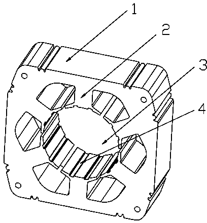
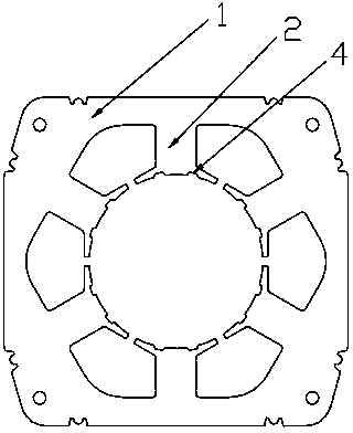
[0013] Example 1: one of the structures of the present invention, see figure 1 , 2 , it has a stator core 1 formed by stacking multiple silicon steel punches, on which windings are provided (the windings are not shown in the figure, which is a conventional technology), and a central hole 3 is also provided in the stator core, around the center The hole is provided with 6 tooth crowns 2, especially: 2 axial grooves 4 are opened on the arc end face of each tooth crown 2, which is mainly suitable for motors with an odd number of slots ZO in the unit motor (1 Axial grooves, suitable for motors with an even number of motor slots ZO).

[0014] In this embodiment, the groove 4 on the tooth crown 2 of the stator core is a full-length through groove.

[0015] In this embodiment, the groove 4 on the tooth crown 2 of the stator core has a rectangular structure.

example 2

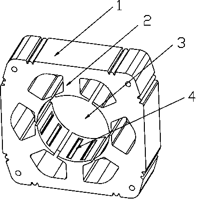
[0016] Example 2: two structures of the present invention, see image 3 , it has a stator core 1 formed by stacking multiple silicon steel punches, on which windings are provided (the windings are not shown in the figure, which is a conventional technology), and a central hole 3 is provided in the stator core, surrounding the central hole There are several tooth crowns 2 structures, especially: two axial grooves 4 are opened on the circular arc end surface of each tooth crown 2 .

[0017] In this embodiment, ribs are provided at both ends of the groove 4 on the tooth crown 2 of the stator core (it is also possible that only one end is provided with a rib, and the other end runs through).

[0018] In this embodiment, the groove 4 on the tooth crown 2 of the stator core is semicircular.

[0019] The analysis of the design principle of the present invention is as follows: a brushless DC motor with grooves on the crown of the stator adopts silicon steel stamping crowns of the sta...


PUM


Abstract

The invention relates to the technical field of motors, in particular to a stator used in a brushless direct current motor and used for reducing fundamental wave cogging torque. The stator is provided with a stator iron core formed by overlaying a plurality of pieces of stamped silicon steel. A winding is arranged on the iron core, a center hole is formed in the stator iron core, and a plurality of crown structures are arranged around the center hole. The stator is characterized in that at least one axial groove is formed in the arc end face of each crown. According to the stator used in the brushless direct current motor and used for reducing the fundamental wave cogging torque, the fundamental wave cogging torque is effectively reduced, the motor power is improved, the motor is convenient to start, and low in vibration and noise, and the stator is mainly applicable to the improvement of the brushless direct current motor.

Description

technical field [0001] The invention relates to the technical field of motors, in particular to a stator for reducing fundamental wave cogging torque in a brushless DC motor. Background technique [0002] The research on brushless DC motors in various countries in the world today has never stopped, and new scientific research achievements of brushless DC motors are constantly emerging. There are many types of structures, but so far, brushless DC motors still have fundamental wave cogging torque. The problem of large reluctance torque directly affects a series of problems such as the starting performance of the motor, energy consumption, vibration and noise, and control signal sensor distortion. Contents of the invention [0003] The purpose of the present invention is to solve a series of problems caused by the large fundamental cogging torque in the existing brushless DC motor, and provide a stator for reducing the fundamental cogging torque in the brushless DC motor. ...

Claims


Application Information

Patent Timeline
Patent Type & Authority Applications(China)
IPC IPC(8): H02K1/16H02K29/00
Inventor 杨百昌方泽云曹礼建文耿肖锐陈宇袁庆庆
Owner HUANGSHI DONGBEI ELECTRICAL APPLIANCE
Why Eureka
Try Eureka