Frequency modulation method for full-bridge inverter circuit

A full-bridge inverter circuit and frequency modulation technology, which is applied in the direction of converting AC power input to DC power output, electrical components, and output power conversion devices, which can solve problems such as low power factor and efficiency, high noise, and complex control. , to achieve the effect of improving power factor and efficiency

Inactive Publication Date: 2014-07-30
UNIV OF ELECTRONIC SCI & TECH OF CHINA
View PDF5 Cites 5 Cited by
  • Summary
  • Abstract
  • Description
  • Claims
  • Application Information

AI Technical Summary

Problems solved by technology

Frequency modulation and power modulation have the advantages of being simple and easy to operate, but its disadvantages are also obvious. When the power applied to the fixed load is lower, the switching frequency of the inverter circuit needs to be higher, and the power factor and efficiency are lower.
Existing solutions such as phase-shift power modulation and pulse density power modulation control methods are quite complicated to operate. The efficiency of the lagging arm is poor when the phase-shift power modulation outputs low power. The pulse density power modulation has large noise and poor heating. uniform problem
Chopper power regulation can solve the power output problem under various loads, but chopping power regulation needs to add a lot of extra equipment, making the control more complicated, increasing the cost and reducing the efficiency of the system

Method used


Image

  • Frequency modulation method for full-bridge inverter circuit
  • Frequency modulation method for full-bridge inverter circuit
  • Frequency modulation method for full-bridge inverter circuit

Examples


Embodiment Construction

[0016] Below in conjunction with accompanying drawing, describe technical scheme of the present invention in detail

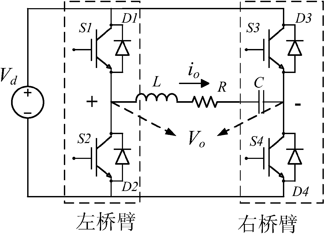
[0017] Such as figure 1 As shown, the present invention uses reverse conduction IGBT switch tubes S1, S2, S3, and S4 to form a full-bridge inverter circuit, and the full-bridge inverter circuit is connected to the power supply voltage V d , where S1 and S2 are connected to form the left bridge arm, S3 and S4 are connected to form the right bridge arm, and the left bridge arm is connected to the right bridge arm through inductance L, resistor R and capacitor C in turn; specifically: the collectors of S1 and S3 are connected to the power supply Voltage V d The positive pole of S1; the emitter of S1 is connected to the collector of S2; the emitter of S1 is connected to the emitter of S3 through inductance L, resistor R and capacitor C in turn; the emitter of S3 is connected to the collector of S4; the emitter of S2 and the collector of S4 The emitter is connecte...


PUM


Abstract

The invention relates to electronic circuit technologies, in particular to a frequency modulation method for a full-bridge inverter circuit. According to the frequency modulation method for the full-bridge inverter circuit, a reverse conducting type IGBT switching tube S1, a reverse conducting type IGBT switching tube S2, a reverse conducting type IGBT switching tube S3 and a reverse conducting type IGBT switching tube S4 are used for forming the full-bridge inverter circuit, a full-bridge modulation mode is adopted when the output power of the full-bridge inverter circuit ranges from 56% to 100%, an asymmetric frequency modulation mode is adopted when the output power of the full-bridge inverter circuit ranges from 25% to 56%, a half-bridge modulation mode is adopted when the output power of the full-bridge inverter circuit is smaller than 25%. The frequency modulation method for the full-bridge inverter circuit has the advantages that through a segmented power modulation mode, the power factor and efficiency of devices are greatly improved. The frequency modulation method is especially applicable to full-bridge inverter circuit frequency modulation.

Description

technical field [0001] The invention belongs to electronic circuit technology, and in particular relates to a frequency modulation method for a full-bridge inverter circuit. Background technique [0002] In the application of induction heating power supply, the traditional voltage-type full-bridge inverter power adjustment method is symmetrical frequency modulation power adjustment. When the switching frequency of the inverter increases from the natural resonant frequency of the equipment, the output power of the equipment will decrease. Frequency modulation and power modulation have the advantages of being simple and easy to operate, but their disadvantages are also obvious. When the power applied to the fixed load is lower, the switching frequency of the inverter circuit needs to be higher, and the power factor and efficiency are lower. Existing solutions such as phase-shift power modulation and pulse density power modulation control methods are quite complicated to operat...

Claims


Application Information

Patent Timeline
IPC IPC(8): H02M7/5387
Inventor 毕闯向勇胡金刚李亚君
Owner UNIV OF ELECTRONIC SCI & TECH OF CHINA
Why Eureka
Try Eureka