A kind of led driver chip, led driver circuit and led lamp
A technology of LED driver and LED lamp group, applied in the field of lighting, can solve the problem of inaccurate judgment of current adjustment range and so on
- Summary
- Abstract
- Description
- Claims
- Application Information
AI Technical Summary
Problems solved by technology
Method used
Image
Examples
Embodiment 1
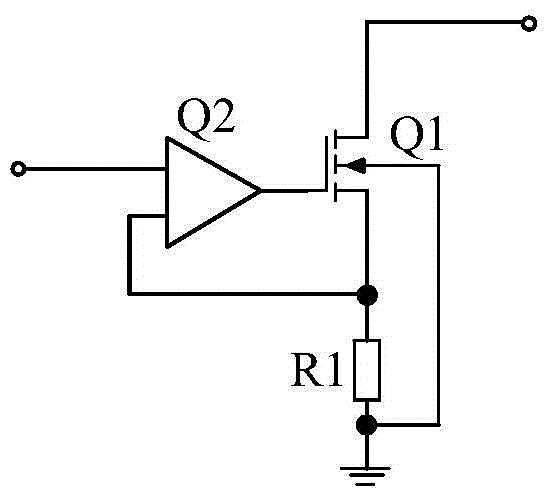
[0025] figure 1 The module structure of the LED driver chip provided by this embodiment is shown. For the convenience of description, only the parts related to this embodiment are shown, and the details are as follows:
[0026] The LED driver chip provided in this embodiment is connected to the rectifier bridge 10 and the LED lamp group 30 .
[0027] In this embodiment, the number of LED lamp groups 30 may be one or more, and the connection thereof belongs to the prior art, and will not be repeated here.
[0028] The LED driver chip also includes a control module 20, the output end of the rectifier bridge 10 is connected to the input end of the LED lamp group 30, the output end of the LED lamp group 30 is connected to the input end of the control module 20, and the output end of the control module 20 is connected to the rectifier bridge 10 the DC input terminal.
[0029] Specifically, the AC input end of the rectifier bridge 10 is connected to the AC mains, and the AC mains ...
Embodiment 2
[0046]The implementation of this embodiment is based on the previous embodiment.
[0047] Figure 4 The module structure of the LED driver chip provided by this embodiment is shown. For the convenience of description, only the parts related to this embodiment are shown, and the details are as follows:
[0048] In this embodiment, the detection module 50 includes a clock signal source 52a, a counter 53a and a voltage comparison module 51a;
[0049] The input terminal of the voltage comparison module 51a is the input terminal of the detection module 50, the enable terminal and the input terminal of the counter 53a are respectively connected with the output terminal of the voltage comparison module 51a and the output terminal of the clock signal source 52a, and the output terminal of the counter 53a is the detection module output of 50;
[0050] When the output voltage of the rectifier bridge 10 is higher than the preset voltage value, the voltage comparison module 51a controls...
Embodiment 3
[0067] Figure 7 The module structure of the LED driver chip provided by this embodiment is shown. For the convenience of description, only the parts related to this embodiment are shown, and the details are as follows:
[0068] The embodiment of this embodiment is based on the previous embodiment; different from the previous embodiment, this embodiment uses a detection module 50 with a different structure to detect the maximum voltage value of each rectification cycle.
[0069] In this embodiment, the detection module 50 may include:
[0070] Analog-to-digital conversion module 51b, storage module 52b and comparator 53b;
[0071] The input end of the analog-to-digital conversion module 51b is the input end of the detection module 50, the first input end of the comparator 53b and the input end of the storage module 52b are connected to the output end of the analog-to-digital conversion module 51b, and the output end of the comparator 53b is connected The enable terminal of t...
PUM
 Abstract
Description
Claims
Application Information
 - R&D
- Intellectual Property
- Life Sciences
- Materials
- Tech Scout
- Unparalleled Data Quality
- Higher Quality Content
- 60% Fewer Hallucinations
Browse by: Latest US Patents, China's latest patents, Technical Efficacy Thesaurus, Application Domain, Technology Topic, Popular Technical Reports.
© 2025 PatSnap. All rights reserved.Legal|Privacy policy|Modern Slavery Act Transparency Statement|Sitemap|About US| Contact US: help@patsnap.com


