Autofrettage machining device

A processing device and self-stressing technology, which is applied in the direction of fuel injection devices with stress reduction measures, fuel injection devices, special fuel injection devices, etc., can solve problems such as insufficient stroke and pistons that cannot be inserted

Inactive Publication Date: 2014-07-30
DENSO CORP
View PDF12 Cites 3 Cited by
  • Summary
  • Abstract
  • Description
  • Claims
  • Application Information

AI Technical Summary

Problems solved by technology

In such a processing method, due to the shape of the workpiece to be processed (fine holes, short pipes, etc.), various constraints su

Method used


Image

  • Autofrettage machining device
  • Autofrettage machining device
  • Autofrettage machining device

Examples


Embodiment approach

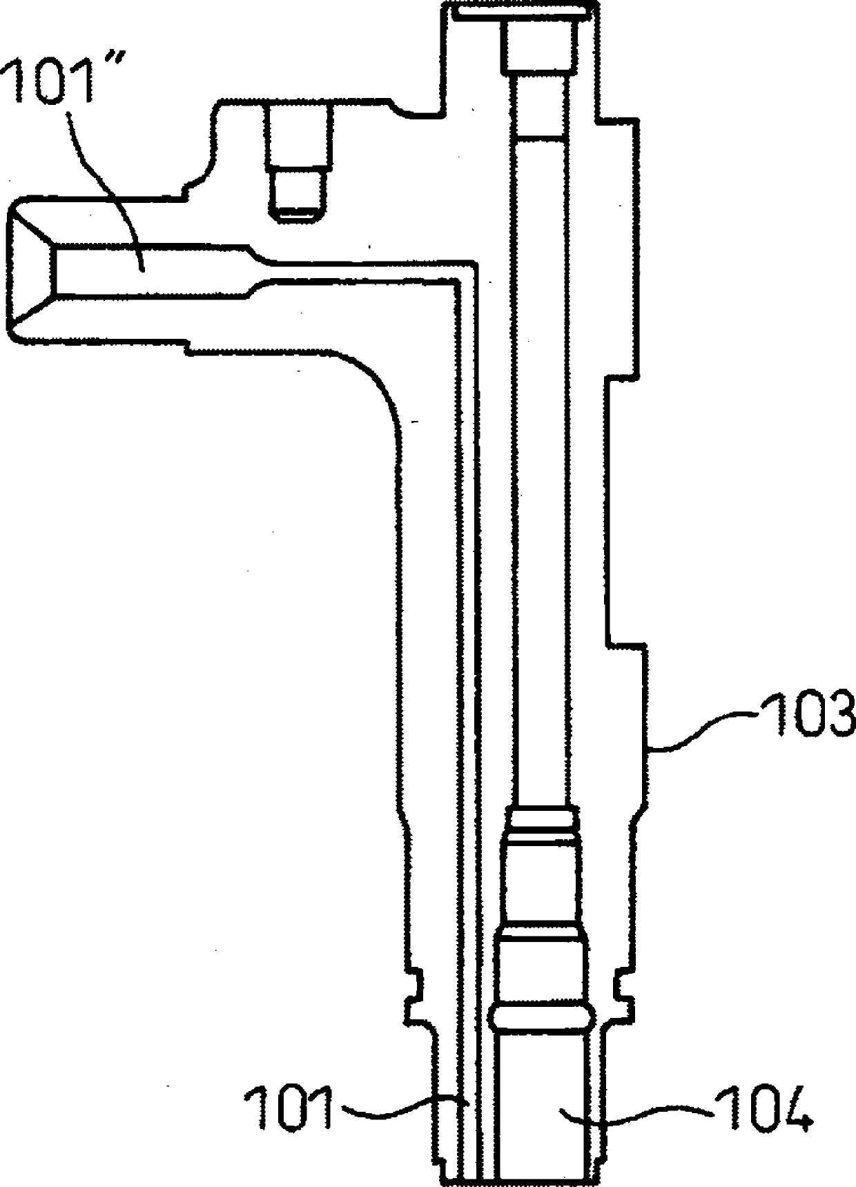
[0114] Figure 12 , Figure 13 It is a schematic sectional view explaining one embodiment of this invention. exist Figure 12 In, workpiece 1 is a high pressure supply pump, in Figure 13 Here, the workpiece 1 is the fuel injection valve main body 103 . Figure 14 is description Figure 13 A schematic oblique view of an embodiment of the present invention.

[0115] in, Figure 12 The high-pressure supply pump 1 for pressure-feeding fuel to the common rail is known from Japanese Patent Laid-Open No. 2010-229924 and the like. Figure 12 The discharge valve is screwed into part 11 and the suction valve is screwed into part 12. The plunger is inserted into the IC inside 13 . The outer periphery of the portion 13 is a cylindrical surface and is not threaded.

[0116] First, an outline of an embodiment of the present invention will be described. In one embodiment of the present invention, in the case where the above-mentioned various constraints exist in the workpiece 1 to b...


PUM


Abstract

Provided is a solution to various limitations caused by product shape and the like. An autofrettage machining device characterized in comprising: a workpiece that is sealed off except for the workpiece end opening and in which a pressurized chamber is filled with a hydraulic oil via the workpiece end opening; a jig capable of being attached and detached from the workpiece, having an internal direct flow channel, and in which the direct flow channel is in communication without leakage with the workpiece end opening via a seal part; a piston for forming a gap having a predetermined average gap size with the inner wall of the direct flow channel provided inside the jig; and a pressurizing unit for driving the piston.

Description

technical field [0001] The present invention relates to a self-stressing processing device, which is used for processing devices such as high-pressure fuel injection pipes and common rails, especially for self-stressing processing under ultra-high pressure. Background technique [0002] As shown in Patent Documents 1 and 2, a processing method (called self-stress processing) is known in which high pressure is applied in a sealed state to leave residual stress in the structure of the material to increase the strength. [0003] That is, in self-stress machining, high pressure is applied inside the workpiece so that the inside of the workpiece is plastically deformed, and the outside of the workpiece is elastically deformed without plastic deformation. Thus, residual compressive stress is applied to the workpiece, and the compressive fatigue strength of the workpiece is enhanced. Such a processing method is used to apply residual compressive stress to components requiring comp...

Claims


Application Information

Patent Timeline
IPC IPC(8): B21D26/033F02M55/02C21D7/12
CPCB23P9/00F02M55/00F02M55/02F02M61/168F02M2200/03F02M2200/8053F02M2200/9061
Inventor 立山健太近藤文男原雄介
Owner DENSO CORP
Why Eureka
Try Eureka