Workpiece fixture

A technology for fixing devices and workpieces, which is used in positioning devices, metal processing machinery parts, metal processing equipment, etc., and can solve the problems of inclined machining surface angle, fixture pressure deviation, different concentric angles, etc., and achieve reliable position setting. The effect of fixing and fixing, minimizing centrifugal force deviation, and reducing displacement phenomenon

Inactive Publication Date: 2016-03-02
辛光子
View PDF7 Cites 1 Cited by
  • Summary
  • Abstract
  • Description
  • Claims
  • Application Information

AI Technical Summary

Problems solved by technology

[0007] In addition, if the shape of the left and right edges of the motor case is not symmetrical, it will inevitably cause deviations in the pressing force of each fixture, so due to the above-mentioned distortion of the workpiece, etc., the processing point of the workpiece and the processing tool will change. The position is not on the same line, and the phenomenon of different concentric angles occurs
[0008] In addition, when the position of the workpiece is changed during the pressurization process, the angle of the processed surface of the workpiece is inclined.
[0009] This not only becomes the main cause of poor processing, but also brings troubles that the position of the workpiece needs to be revised many times in order to maintain the concentric line between the processing tool and the processing hole.

Method used


Image

  • Workpiece fixture
  • Workpiece fixture
  • Workpiece fixture

Examples


Embodiment Construction

[0035] Next, specific structures and effects of the present invention will be described based on the embodiments shown in the drawings.

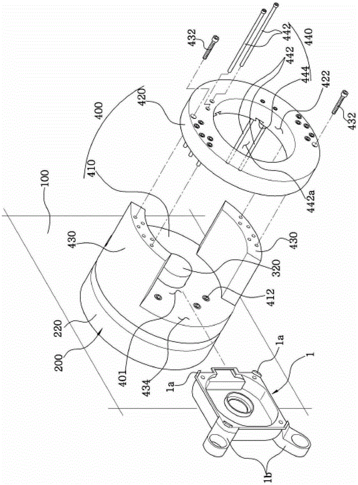
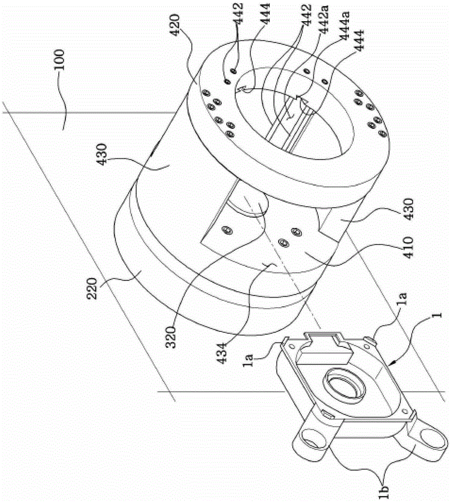
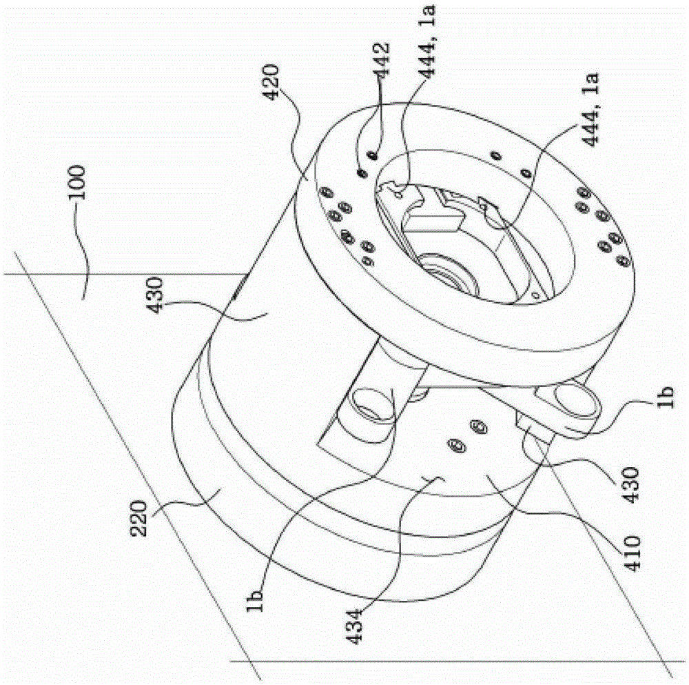
[0036] Such as Figure 1 to Figure 4 As shown, the workpiece fixing device of the present invention generally includes a main body 100 , a rotation driving part 200 , a pressing part 300 and a position setting part 400 .

[0037] Firstly, the main body 100 functions as a shell and a skeleton of the workpiece fixing device, and is configured with a structure suitable for lathe equipment or milling equipment according to the type of processing.

[0038] Therefore, in the drawings of this embodiment, the structure of the main body 100 is not detailed but shown in a simple schematic diagram.

[0039] Such a main body 100 is provided with a rotation drive unit 200 .

[0040] The rotation drive unit 200 includes a rotation motor 210 and a rotation shaft 220 , and rotates a position setting unit 400 described later to rotate the workpiece 1 set o...


PUM


Abstract

The invention relates to a workpiece fixing device. Specifically, by improving the position fixing structure of the workpiece, it can not only prevent the damage of the workpiece during the position fixing process, but also accurately maintain the gap between the processing point of the workpiece and the processing tool. The concentric line of the machine can prevent poor processing and realize rapid and reliable position setting of the workpiece.

Description

technical field [0001] The invention relates to the ability to reliably fix the position of the workpiece during the hole machining process of the workpiece such as the motor casing, thereby preventing the workpiece from being damaged during the pressurization process and preventing the displacement between the processing point and the processing tool. phenomenal technology. Background technique [0002] Usually, after the motor housing made of aluminum is molded by die casting, the hole machining process such as the shaft hole or the bearing hole is performed. [0003] At this time, after setting the position of the workpiece first, in a state where the position is fixed by a jig or the like, machining processes such as chamfering are performed using a machining tool such as a cutting knife. [0004] However, the conventional fixation method using a jig is a method in which a plurality of jigs press and hold the edge of the workpiece in a state where the workpiece is posit...

Claims


Application Information

Patent Timeline
Patent Type & Authority Patents(China)
IPC IPC(8): B23Q3/12B23B31/10B23B31/103
CPCB23B31/10B23B31/103
Inventor 辛光子
Owner 辛光子
Why Eureka
Try Eureka