An on-line detection method for rolling direction offset of hot rolling mill rolls

A technology of rolling direction and detection method, which is applied in the direction of metal rolling, metal rolling, length measuring device, etc., can solve the problems that the shape of the plate cannot be accurately controlled, the quality of the hot-rolled steel plate is troubled, and the rolling control is difficult. Accurate and reliable effect, high promotion and use value, simple and practical effect

Inactive Publication Date: 2015-09-23
HEBEI IRON AND STEEL
View PDF7 Cites 0 Cited by
  • Summary
  • Abstract
  • Description
  • Claims
  • Application Information

AI Technical Summary

Problems solved by technology

This periodic offset brings certain difficulties to the control of rolling, and also causes serious wear of bearings, which also has a serious impact on the service life of rolling parts
If the roll system intersects in medium and heavy plate rolling, this offset will cause camber to increase and it is difficult to eliminate it through HAGC roll gap adjustment, and the shape of the plate cannot be accurately controlled, which restricts the improvement of the yield of the steel plate
[0004] At present, in the actual production process, there has been no real-time and accurate measurement method for the offset state of the roll rolling direction when the rolling mill is working. Reliable offset correction data directly affects production and becomes a problem that plagues the quality of hot-rolled steel sheets, which has not been effectively resolved

Method used


Image

  • An on-line detection method for rolling direction offset of hot rolling mill rolls
  • An on-line detection method for rolling direction offset of hot rolling mill rolls
  • An on-line detection method for rolling direction offset of hot rolling mill rolls

Examples


Embodiment Construction

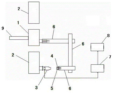
[0024] In the present invention, the archway of the hot rolling mill is used as a reference object, and the light intensity center of the light-permeable circular hole relatively stationary relative to the archway is used as the feature point of the archway position, and the position feature point of the archway is acquired by a CCD camera relatively stationary to the roll during the rolling process By comparing the image with the calibration distance, calculate the real-time physical coordinates of the center of the feature point of the archway, and determine the displacement of the camera lens relative to the rolling direction of the feature point of the archway, so as to obtain the offset of the roll relative to the archway in the rolling direction .

[0025] This approach takes the following steps in concrete implementation:

[0026] (1) Taking the rolling mill archway 2 as a reference object, set the light intensity center of a light-transmitting circular hole 4 that is r...


PUM

PropertyMeasurementUnit
diameteraaaaaaaaaa

Abstract

The invention provides an online detection method for hot mill roller rolling direction offset, and belongs to the technical field of hot mill roller detection methods. The online detection method is used for accurately measuring the offset, in the rolling direction and relative to a housing, of a roller. According to the technical scheme, the hot mill housing serves as a reference object, the light intensity center of a light-permeable circular hole which is fixed relative to the housing serves as the feature point of the position of the housing, in the rolling process, an image of the feature point of the position of the housing is obtained through a CCD camera which is fixed relative to the roller, the real-time physical coordinates of the center of the feature point of the housing is calculated by comparing the image with the calibrated distance, and therefore the offset, relative to the housing and in the rolling direction, of the roller is obtained. The method is simple, practical and accurate and reliable in test result, provides reliable offset correction data for accurate control over the adjustment and the plate shape of a roller system, and has important significance in the increase of the steel plate yield. The method solves the difficult problem that the offset, in the rolling direction, of the roller can not be accurately measured and has extremely-high popularization and use value, wherein the problem has affected production for a long time.

Description

technical field [0001] The invention relates to a method for on-line detecting the offset of hot rolling mill rolls in the rolling direction, and belongs to the technical field of hot rolling mill roll detection methods. Background technique [0002] The roll train of an ordinary four-high hot rolling mill usually includes an upper back-up roll, an upper work roll, a lower work roll and a lower back-up roll arranged in sequence from top to bottom. The two ends of the upper back-up roll and the lower back-up roll are respectively installed on the respective back-up roll chocks, the two ends of the upper work roll and the lower work roll are respectively installed on the respective work roll chocks, the back-up roll chocks and the work roll chocks are both Installed in a frame archway, the gap between the bearing seat and the frame is filled with gaskets, and the roll and its bearing seat are relatively stationary in the rolling direction. Under normal working conditions, the...

Claims


Application Information

Patent Timeline
Patent Type & Authority Patents(China)
IPC IPC(8): B21B38/00
Inventor 张晓力陈文张鹏刘宏强
Owner HEBEI IRON AND STEEL
Why Eureka
Try Eureka